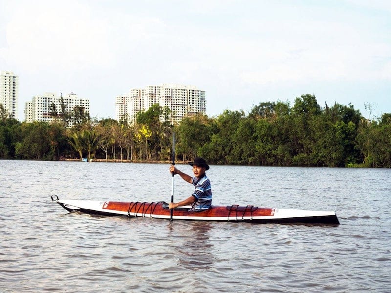
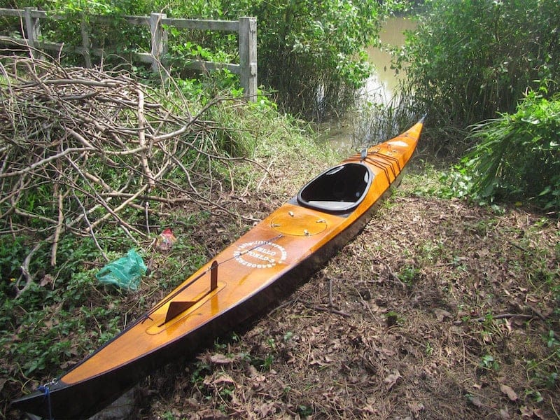
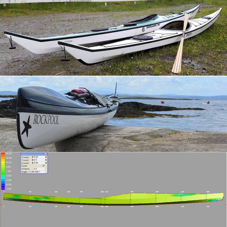
Đầu tiên nói sơ qua về quá trình chuẩn bị cho chuyến đi này. Tôi có trong tay chiếc Serene – 2, tốt hơn hẳn chiếc Serene – 1, ổn định và nhanh nhẹn hơn, có khả năng chở nhiều đồ hơn. Xuồng cũng được trang bị hệ thống điện: tấm năng lượng mặt trời, pin 18650 (25 Amph), đèn, la bàn, hệ thống bơm nước, sạc điện thoại, sạc máy ảnh, sạc cho Garmin, bộ đàm hàng hải cũng như tất cả những thiết bị điện tử khác… Serene – 2 có hệ thống bánh lái hoạt động hiệu quả. Sự chuẩn bị đi sâu vào những chi tiết nhỏ nhất: thay 11 cái cọc lều sắt (dễ rỉ, nặng) bằng 11 chiếc làm bằng nhôm hợp kim (nhẹ, không rỉ, và bám chắc hơn trên địa hình đất cát).
Nồi nấu cơm, bếp… tất cả đều đã được thay bằng loại hợp kim nhôm, nhẹ và không rỉ. Tôi có một chiếc Garmin Touch 25 mới, màn hình cảm ứng, và kinh nghiệm với chiếc máy này thật tuyệt! Điều hay nhất là với cảm ứng (touch), bạn có thể thao tác, zoom in/out bản đồ, đọc thông tin rất nhanh. Điều đó rất có ích cho việc nâng cao situational awareness, nhận thức tình huống, chỉ mất vài giây để đọc thông tin từ thiết bị, đưa ra phán đoán và hành động đúng. Cần phải nói rằng kỹ năng quan trọng nhất với 1 skipper / sailor trên biển là khả năng nhận thức tình huống: ta đang ở đâu, ta đang đối mặt với những gì, ta cần phải làm những gì.
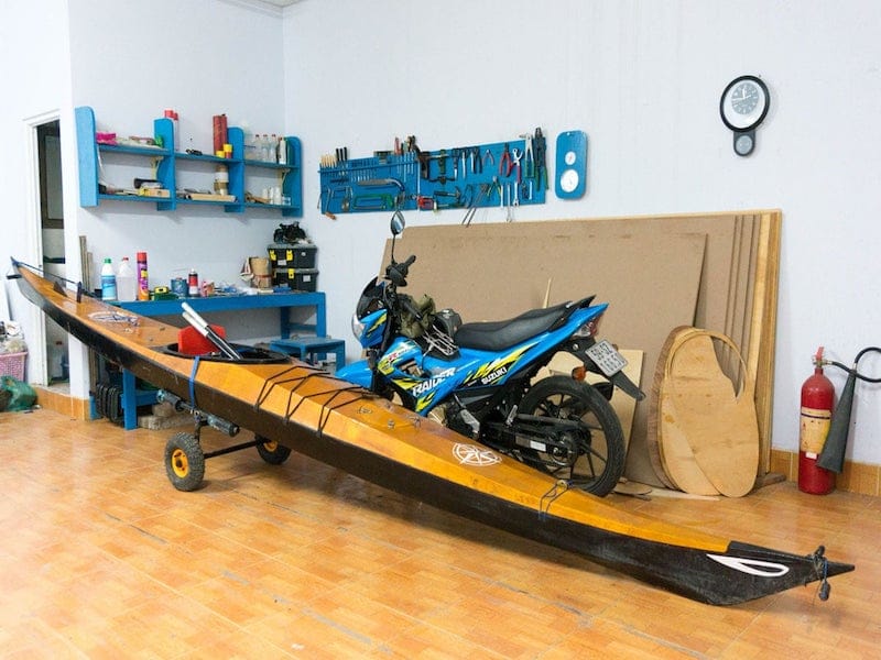
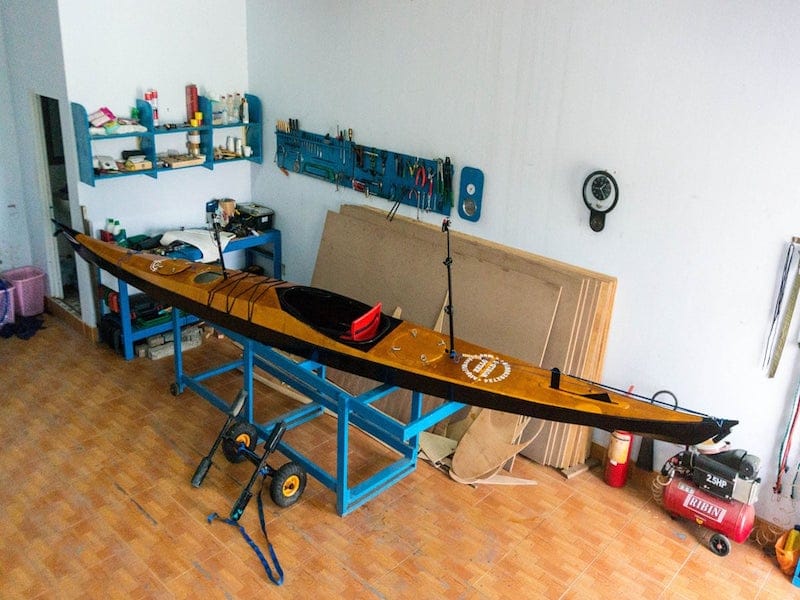
Tôi đóng 1 chiếc xe đẩy (cart) mới, nhẹ hơn, buộc vào phía sau thuyền. Chiếc xe cũng đã được tính toán để có thể tháo rời thành 3 mảnh, xếp vào trong khoang khi cần. Khi đi dọc bờ biển thì không cần thiết lắm, nhưng trong những chuyến vượt biển xa, chiếc xe sẽ được xếp gọn vào trong khoang, cải thiện tính ổn định và an toàn của kayak. Nói kỹ hơn về chiếc xe đẩy, đây là một công cụ không thể thiếu, thuỷ triều sông Cửu Long khi dâng, khi cạn chênh nhau hàng cây số, cần có chiếc xe để kéo thuyền lên bờ, vào sâu trong đất liền, kiếm chỗ cắm trại tiện nghi và an toàn cho một đêm nghỉ ngơi đầy đủ, và hạ thuỷ chiếc thuyền trở lại sáng ngày hôm sau.
Đã có một số sai lầm khi đóng cái xe đẩy mới, nhẹ và gọn hơn này, và nó để lại hậu quả kinh khủng. Cũng bởi tôi “tham” 1 chuyến hành trình tiện nghi hơn năm trước, nên đã chất lên thuyền khá nhiều đồ ăn nước uống, kể cả 1 kg chanh & 1 kg đường để làm nước giải khát cho cái hành trình vào dịp cao điểm nắng nóng này. Mùa mưa đã chính thức bắt đầu, nhưng gió Nam vẫn còn đang yếu, dông gió chỉ hơi nhỏ, không có gì đáng ngại. Nhưng lại phạm sai lầm khi không theo thói quen (bắt đầu hành trình vào dịp trăng tròn) thuỷ triều ngày hôm đó biên độ có hệ số (tidal coefficient) khoảng 109, một giá trị rất cao (cao nhất max = 120).
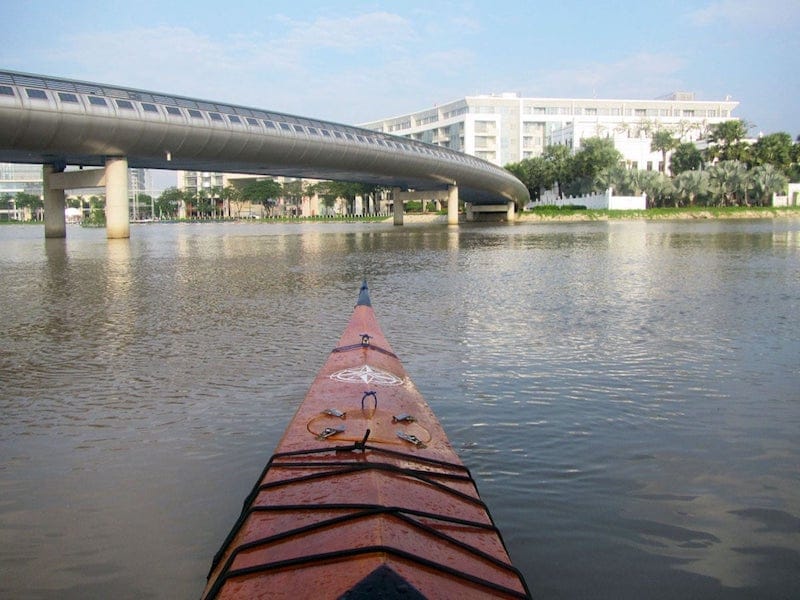
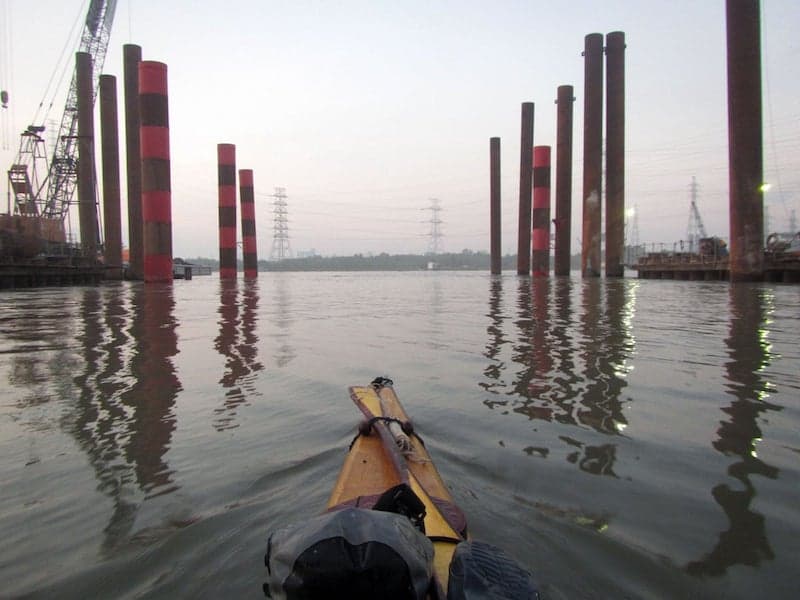
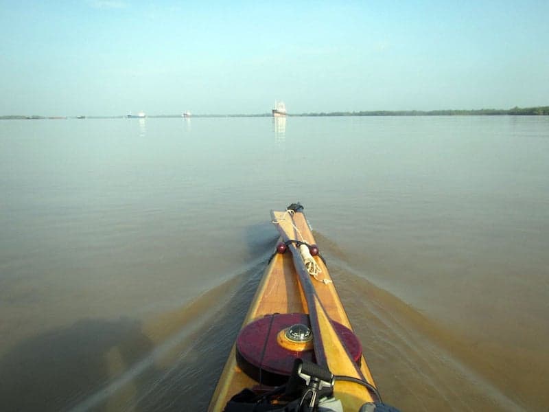
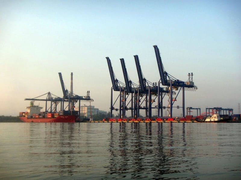
Đã dự tính trong đầu 1 hành trình an toàn hơn, có tính trải nghiệm nhiều hơn hành trình năm ngoái (năm ngoái dường như là một cuộc dạo chơi điên rồ và liều lĩnh), nhưng phải nói sự chuẩn bị thể lực năm nay không được tốt bằng, và một số bài học rút ra từ hành trình năm ngoái không được áp dụng đúng cho lắm! Khởi hành từ 5h sáng, xuôi từ Nhà Bè, qua cảng Hiệp Phước, ngã 3 sông Soài Rạp – Vàm Cỏ, xuống đến Vàm Láng diễn ra suôn sẻ, thuyền đi rất nhanh và êm, chưa đến 11h trưa là tôi đã qua cảng cá Vàm Láng, tổng cộng khoảng 44 km trong vòng chưa đến 6h. Dừng ăn trưa ở đây trước khi tiếp tục hành trình.
Từ Vàm Láng đến Tân Thành (điểm cắm trại dự tính cho ngày đầu tiên) chỉ còn khoảng 12 km, đang vui mừng nghĩ rằng sẽ hoàn thành ngày đầu tiên không lâu nữa, thì thuỷ triều lên, gió và sóng cũng mạnh dần lên khoảng 2, 3 feet. Trực giác đầu tiên là đoạn hành trình này giống hệt đoạn vượt cửa Trần Đề năm ngoái, thuỷ triều dâng với một sức mạnh khó có thể tượng tượng, vận tốc nước trên 5 kmph, cộng thêm với gió và sóng ngược chiều. Tính tổng hoà các yếu tố, dù cố gắng rất lớn, vận tốc đi được < 2 kmph. Kinh nghiệm nếu gặp tình huống này là nên kiếm chỗ nghỉ ngơi, đợi chừng vài ba tiếng cho cái cao trào khó khăn qua đi rồi mới tiếp tục.
Bởi chẳng ích gì nếu tiếp tục chèo với tốc độ rùa bò và hao sức như thế. Nhưng cái sự hăng hái buổi sáng còn vương vất lại khiến tôi tiếp tục chèo thêm 5, 6 km trong vòng hơn 3 tiếng, khá là mệt mỏi. Trong quãng thời gian này, thuyền lật (capsize) 2 lần. Phải nói rõ là việc lật thuyền (capsize) với kayak không phải là điều gì tệ hại như với các loại thuyền khác. Kayak được chế tạo và trang bị để capsize và recover. Lần capsize thứ nhất, tôi recover bằng 1 kỹ thuật “balanced brace”, thân người nằm ngang mặt nước, được đỡ cho nổi bằng chiếc áo phao, thuyền nghiêng khoảng hơn 100 độ, dùng sức của hai tay và mái chèo lật thuyền đứng trở lại.
Lần lật đầu khiến lần thứ hai đến một cách dễ dàng và bất ngờ hơn (vì lẻ một số nước đã vào bên trong khoang, khiến thuyền trở nên nặng hơn). Một con sóng chỉ chừng 1m lật thuyền, đánh tôi văng ra khỏi xuồng, không phản ứng kịp. Lóp ngóp bật cái công tắc điện chạy máy bơm rồi leo vào thuyền trở lại, tiếp tục chèo đi. Nhưng lực chèo khá nặng (do thuyền đã vào nước), nên quyết định dừng cái “thử nghiệm” về cái khả năng an toàn của thuyền ở đây, dừng lại đúng ở điểm cắm trại năm ngoái dưới chân một con đê biển! Kiểm tra sau đó cho thấy tất cả khoang thuyền ngập đầy nước, và như thế chứng tỏ độ ổn định của Serene – 2 tốt hơn tôi dự kiến.
Và điều đó cũng chứng tỏ toàn bộ hệ thống pin, điện, máy bơm, dù ngập hoàn toàn nhiều giờ liền trong nước biển vẫn hoạt động tốt, hộp chứa pin kín nước tuyệt đối, không có một vụ đoản mạch hay cháy nổ nào xảy ra! Kết thúc ngày chèo thuyền đầu tiên khoảng hơn 3h chiều một cách đầy vui vẻ và hài lòng, nếu không có một sự cố ngay sau đó! Trong lúc bỏ thuyền lên xe đẩy và kéo lên bờ, chiếc xe đẩy gãy một bên bánh! Không thể tiếp tục hành trình mà thiếu cái xe đẩy này, như đã nói trên, cần phải có cái xe để vận chuyển chiếc xuồng từ mép nước sâu vài km vào trong bờ và ngược lại… tôi quyết định huỷ hành trình ngay tại đây!
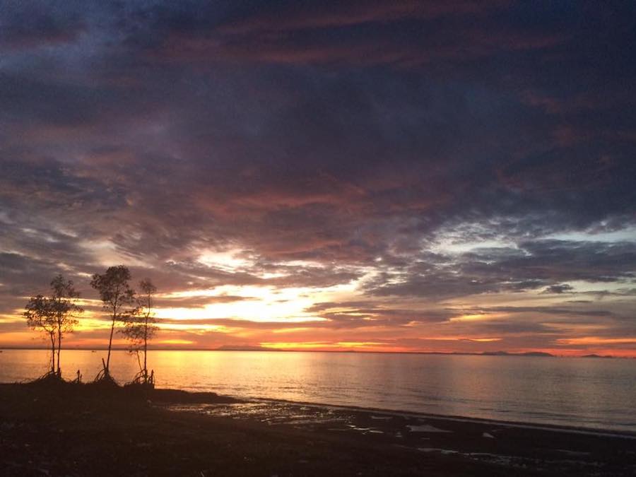
Thất vọng và chán nản vô hạn, chẳng thiết nấu cơm ăn, cắm lều, ăn vài lát bánh mì và đồ hộp! Ngồi hồi lâu bên bờ biển, ngắm những ánh sao lung linh của một đêm không trăng. Những vì sao à, các người lấp lánh, phong phú và hấp dẫn thật đấy! Nhưng sự phong phú của các người cũng không thể nào so được với sự phong phú đầy mầu sắc của tâm hồn tôi đâu! Nhiều suy nghĩ miên man rồi chìm vào giấc ngủ. Sáng hôm sau, cố tình ngủ nướng đến hơn 9h sáng, đợi cho thuỷ triều lên để diễn lại cái kinh nghiệm ngày hôm qua. Bỏ bớt một số đồ ăn nước uống cho nhẹ thuyền, chèo hơn 6 km còn lại đến Tân Thành trong thuỷ triều đang lên.
Trên đường đi, cố tình lật thuyền 6, 7 lần nữa để thực tập kỹ năng “balanced brace” cho kỹ càng hơn, chẳng mấy khi rơi được vào tình huống thuỷ triều và sóng gió khó khăn như thế này! Học thêm được một số kinh nghiệm về lập lịch hành trình và xử lý tình huống dọc đường. Nếu không vì chiếc xe đẩy hỏng thì có lẽ tôi đã tiếp tục hành trình, chấp nhận học thêm một số kinh nghiệm “xương máu” dọc đường đi, để hiểu thêm về dông tố, về sóng gió, thuỷ triều… chẳng có bài học nào mà không phải trả giá. Lên bờ ở Tân Thành, chỉ mất chừng 30 phút để kiếm chiếc xe tải, chở thuyền về lại Nhà Bè, Sài Gòn, kết thúc một hành trình “chết yểu”!