
It’s time to move on to a new kayak design. Lessons learnt from my last failed trip signifies the necessity for a boat design that is geared toward a wide range of self – rescue actions such as: balanced brace, roll and wet – entry. Thanks to the very dynamic world – wide sea – kayak community, which constantly invents and improves various techniques, I’ve updated myself to some newer self – rescue techniques which I consider to be critically important for long cruising trips.
My previous boat, Serene – 2 has some obvious shortcomings though: initial stability is still slightly problematic, especially for reentry; the electricity system, though working very well, is hard to repair or upgrade, this is due to my inexperience with electrical wiring. I would incorporate into this kayak design various small improves here and there: the storage compartments and hatches would be rearranged to better utilize the boat’s volume, a new rudder system with better responsiveness, etc…
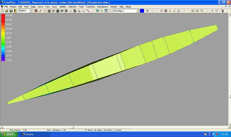
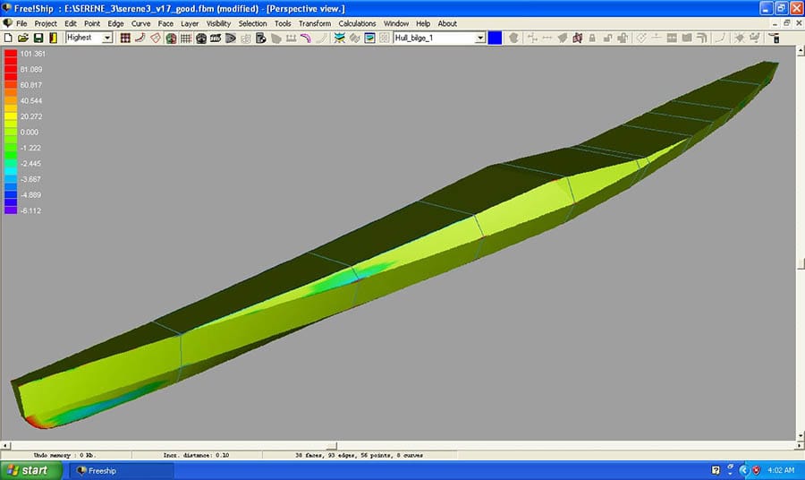
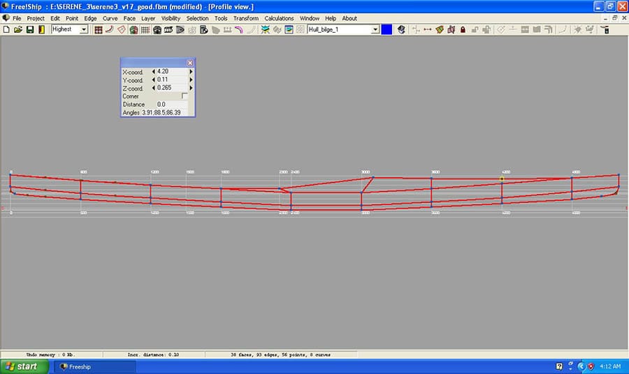
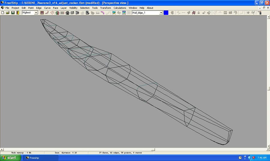
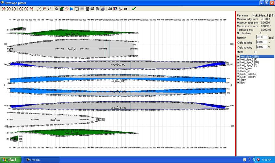
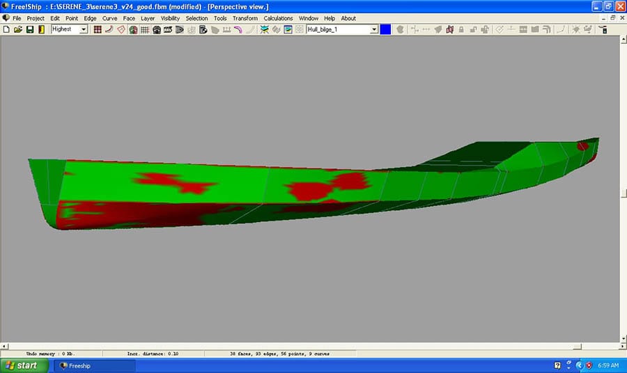
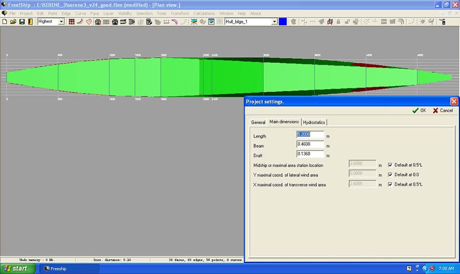
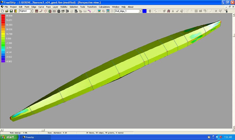
For the last 2 months, most of my free times is directed toward working with FreeShip, the very helpful boat – designing software. Some design parameters: LOA: 5.2m (17′), Beam: 46 cm, Displacement: 120 kg, Cp (prismatic coefficient): 5.3, S (wetted surface): 1.95, Cb (block coefficient): 0.39, Cw (waterplane coefficient): 0.7… The most important change compared to Serene – 2 is a significant increase in rocker, the boat is now much curvy, having the mid section deeper seated in water.
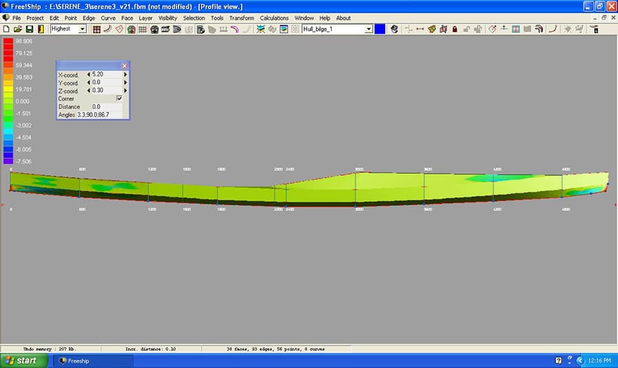
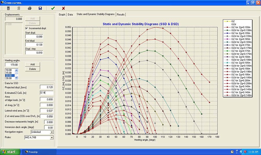
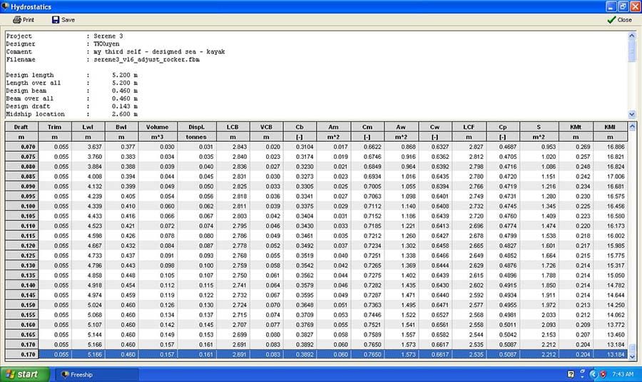
Also, the deck height right after the cockpit is reduced, so that climbing in the kayak would be easier. The hull’s upper bilges now have much more flare, especially at the 2 ends, to help improving secondary stability, that also has Cp (prismatic coefficient) increased to about 0.52 ~ 0.53, a value usually seen on a fast cruising kayak, unlike the quite – low value of 0.5 on my previous Serene – 2. Transverse metacentric height – Kmt increased to 26 ~ 27 cm, which indicates satisfactory initial stability.
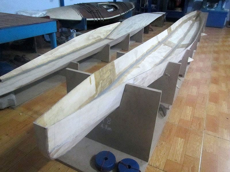
Thus, Serene – 3 is designed with a shift to (primary and secondary) stability concerns. Directional stability (reflected by the Cb – block coefficient value of 0.39) is ensured with an improved rudder system. The beam is slightly widen to 46 cm, and LOA stays at 17 feet. The 5.2m length is an important factor, cause it could entirely fit into a 4 meter truck, which could be easily hired to transport the boat if needed, otherwise at 18 feet, I would need a larger truck, which could be hard to find.
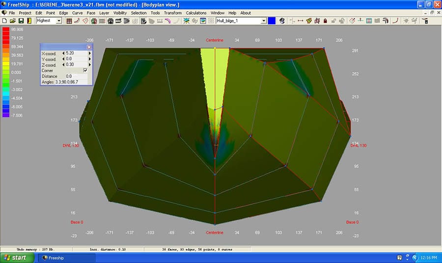
The hull features a deeper V – bottom, something similar to that of the Illorsuit. In all three Serene – 1, 2, 3 designs, I’ve always tried to combine deep V – hull with a narrow beam, something until now I’ve only partially succeeded. Various other improves would be incorporated into this boat. I would build different hatches with big silicone gaskets, to completely solve the water leaking problem (hopefully). Also, there would be 3 hatches along the kayak, to better utilized the storage volume inside.
There’re so many minor improves here and there, and lots of design considerations too, to maximize the usability of the kayak under various real – world conditions. The aft deck is lowered a bit, to facilitate climbing in the cockpit once thrown own by a complete capsize. There’re two deep – water reentry techniques that I was considering possible with this boat design. Wet – reentry has been a shortcoming of previous designs, being too slim and unstable to make an easy access.
This is not a kayak specially tailored for rolling, but Serene – 3 is designed with concerns of balance – brace and rollings in mind. At the moment, I’m not too sure about its capability to roll under full load and heavy sea conditions, but I’m quite confident for its easy recovering in brace actions. Also, the hatches’ design has been reviewed and modified, to improve their water – tight capability, I’m putting great hope in the new gaskets which would be made by silicone molding to accommodate the hatches.
Also, there would be 3 hatches, all big (no small day hatch) to better utilize the internal containing volume. The rudder design is also reviewed and altered, I need lighter pedaling, and quicker overall responsiveness for the rudder actions, a new type of rudder post, new layout for control cabling too. The electronic system would received a bunch of improves in building techniques, decoupling the whole system into several separable components, to make maintenance and repair easier later on.
Finally, I managed to have some time slots to start the kayak building. Works would be carried out mostly at weekends, and hopefully, the boat could be finished within this year. After much hesitations, procrastinations, and considerations into the very details, I’ve incorporated quite some “innovations” into the final design, as well as some “simplifications” to ease the building process. I “hope” this is also my “last” stitch – and – glue boat, the 6th of “the fleet”, seems to be a lot already!
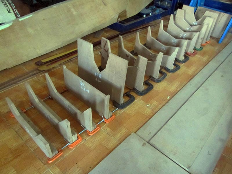
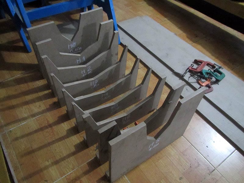
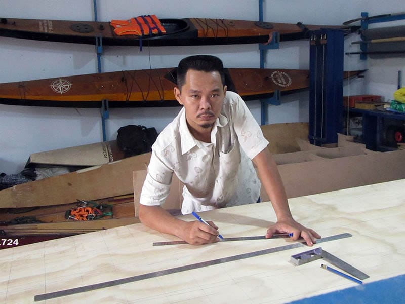
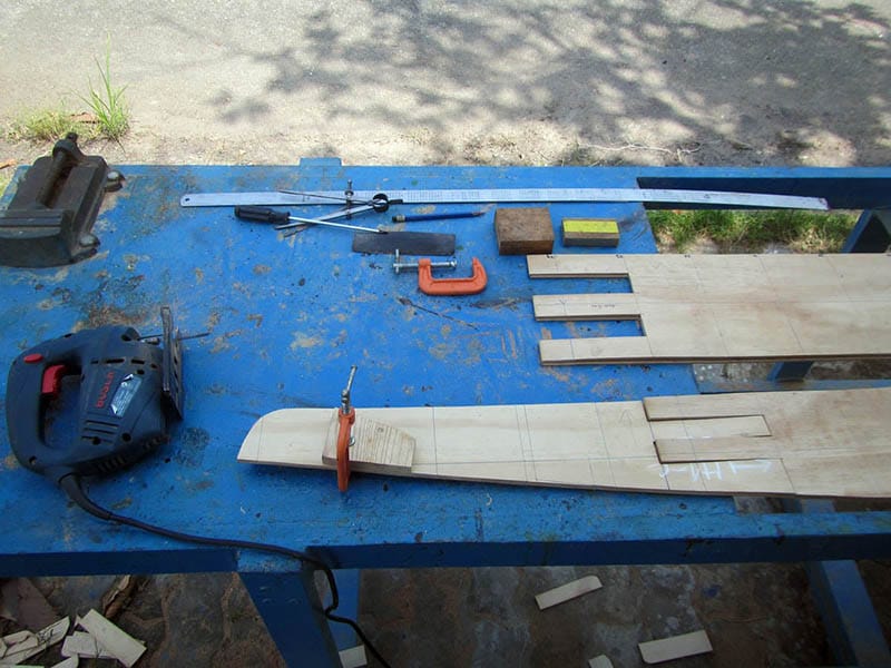
The past 2, 3 weeks were spent mostly on reviewing, fine – tuning the design, “rehearse” the overall building techniques and process. This is a design that consumes my brainstorm the most! Many building steps could be done very quick now, as they have been done 5, 6 times already. So I would skip documenting in various parts, as they are all similar as in my previous boats, only to highlight things that are different. First is setting up the molding stations, cut from MDF as usual.
There would be 9 molding stations (female type) for the hull, and only 4 stations for the deck, each positioned 0.6m apart. One of my last changes to the deck was modifying its sides’ “slope” to 45 degrees, the deck would have lots of “flare” in the inverted position, that’s to make rolling easier. Once the boat is up – side – down and the deck becomes the bottom, so a “stable” full – shape deck wouldn’t be good for practicing kayak rolling. And I guess it could give some help to the boat’s windage too.
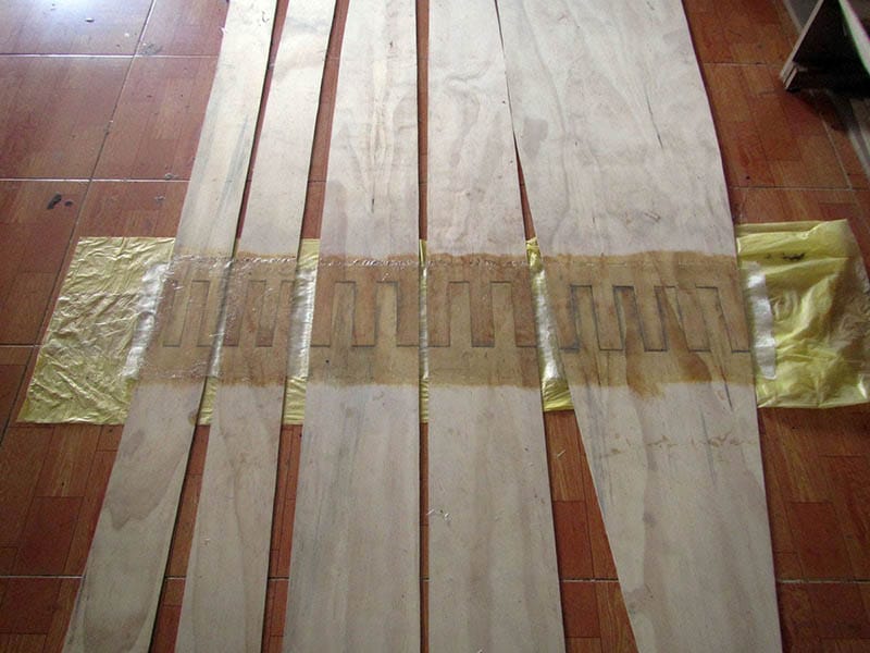
The progress is really slow lately, several weeks passed, but little get done! Things started moving anyhow, I “quickly” transfer the “offset tables” onto the plywood boards, draw all the bilges, bulkheads, and other parts. The greatest thing of all is that now I’ve purchased very good sheets of plywood, not truly marine – grade (there’s no such in Vietnam), but high – grade water – resistance ones. I could feel it when do the sawing, the boards are quit tough, not fragile as with my previous ply!
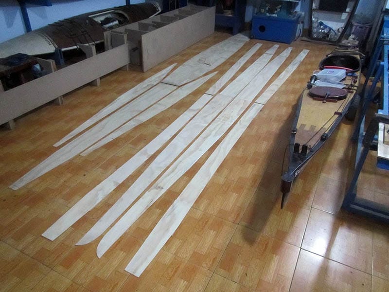
There would be an immediate consequence with the new plywood, I would just use less epoxy to pre – fill the boards, and since the boards is stiffer, the glassing would be done on the outside only, that would significantly save the boat weight, I hope. All drawing is completed quickly, I finished in just less than one day, next come the steps of cutting and jointing the bilges. Everything has been done many times before already, so I didn’t have to think or consider things much, just repeat it!
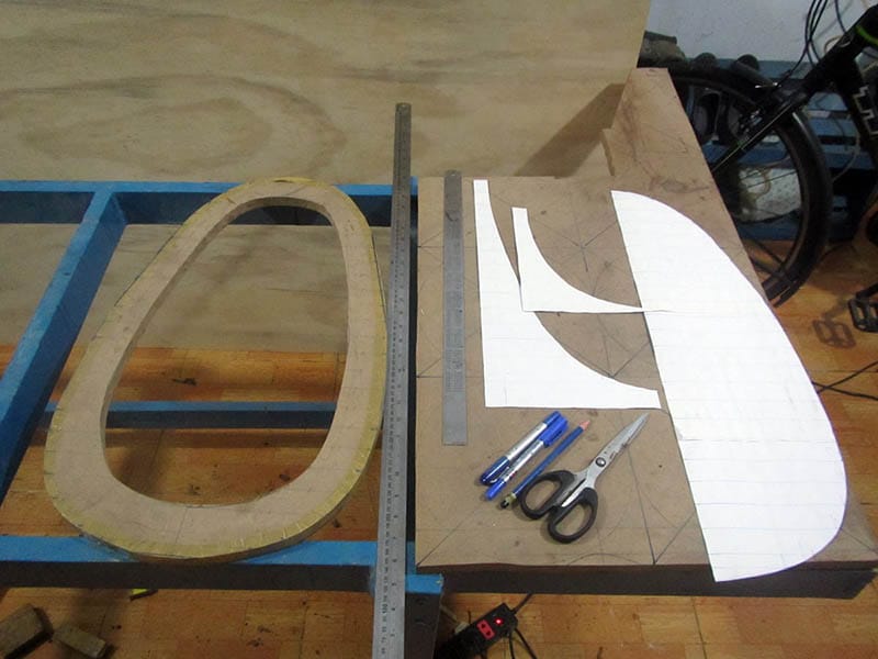
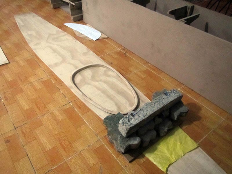
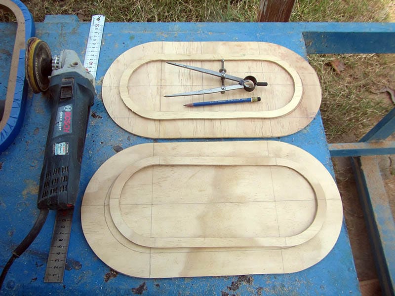
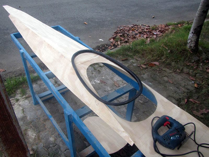
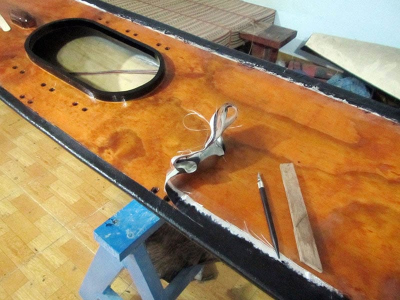
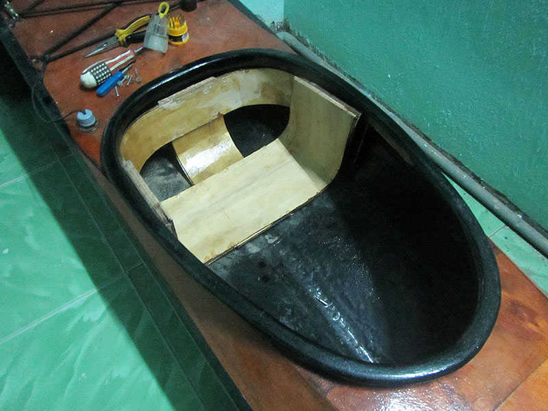
4th image: the cockpit coaming frame cut from a piece of 18 mm MDF. This cockpit is drawn using the mathematic formula mentioned in my last post. It came very closed to the shape of Serene – 2‘s cockpit, but slightly smaller on each sides by about 5 mm, so my existing spray skirt should fit tightly with this new coaming (on Serene – 2, it’s too tight). The coaming would be constructed from 2 layers of 4 mm plywood, and I would later omit out the (a bit tricky) glass reinforcement on this part!
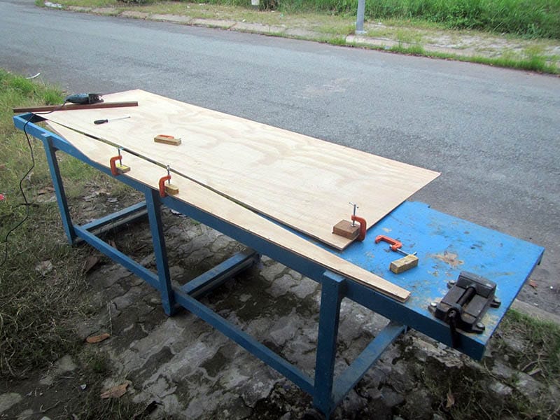

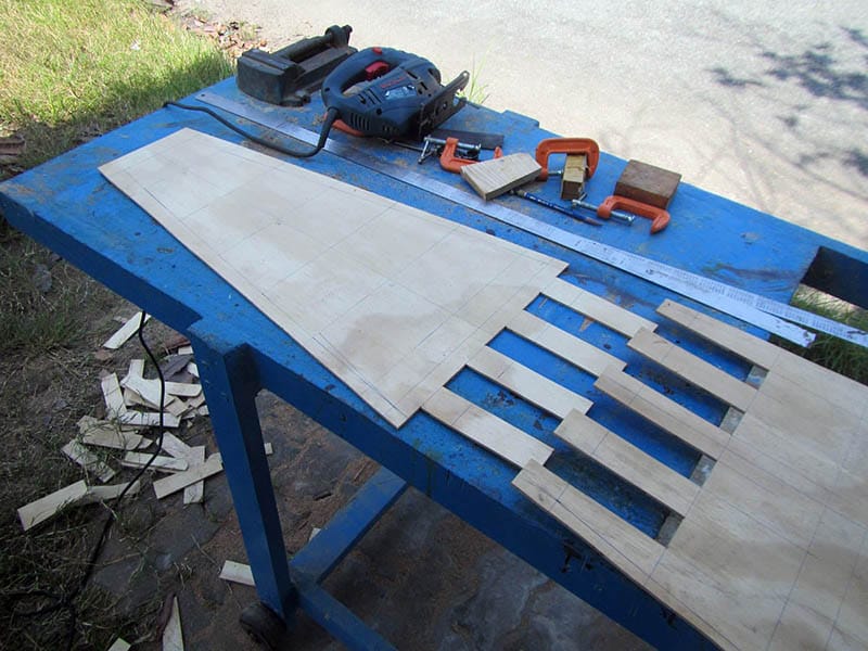
Next is jointing the plywood pieces: 8 joints for the hull, and just 1 for the deck, to form the bilges that would build up into the boat shape. For the 2 pairs of hull’s bilges, I flip one pair by 180 degree when drawing on the boards, so that to distribute the joints at different places across the boat length, and not to concentrate too much joints into one proximity. That old boatbuilding carpenter’s trick is not completely necessary with modern building techniques, but it’s nice to do so anyway.
The tried – and – true technique of straight finger joint is used as always. The straight joints are easy to cut, and most importantly much easier to be aligned following a straight line for all the jointing parts, so that to make sure all the bilges would be jointed into the correct shapes. All the joints are treated carefully, first is applying a layer of thinned epoxy (using xylene as a solvent, for the substance to penetrate deeply into the plywood), then gluing with epoxy, then a layer of glass on the internal side.
I beveled the edges of the deck parts a bit (at 45 degrees), so that they would fit tightly and nicely together forming straight seam lines. But that’s not applied to the hull, where the cursive seam lines don’t like very thin edges. Experiences from my previous boats showed that, it’s best just to use the squared edges, the thin edges doesn’t stay on each other very well, and would deform, distort the seam lines! You would later just apply thickened epoxy on both sides (in and out) of the seams!
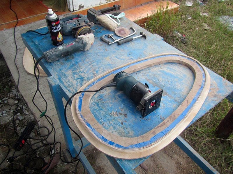
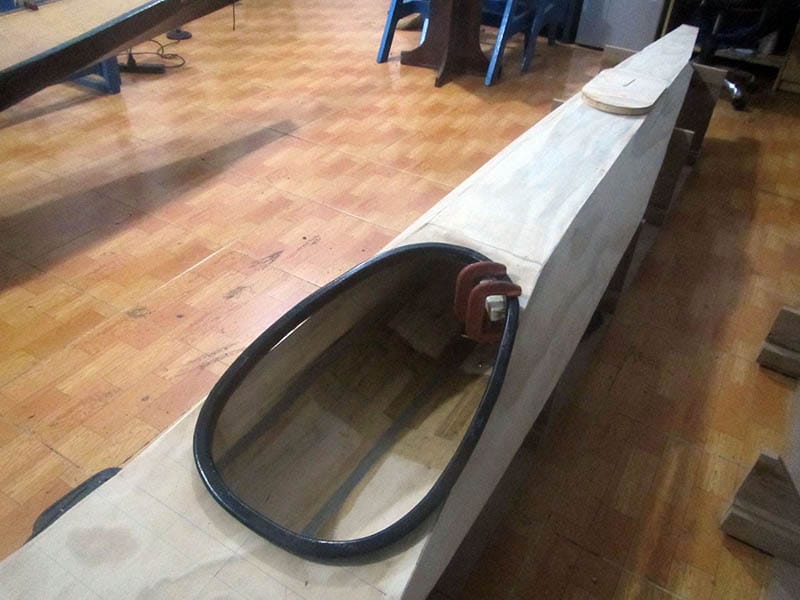
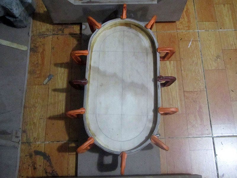
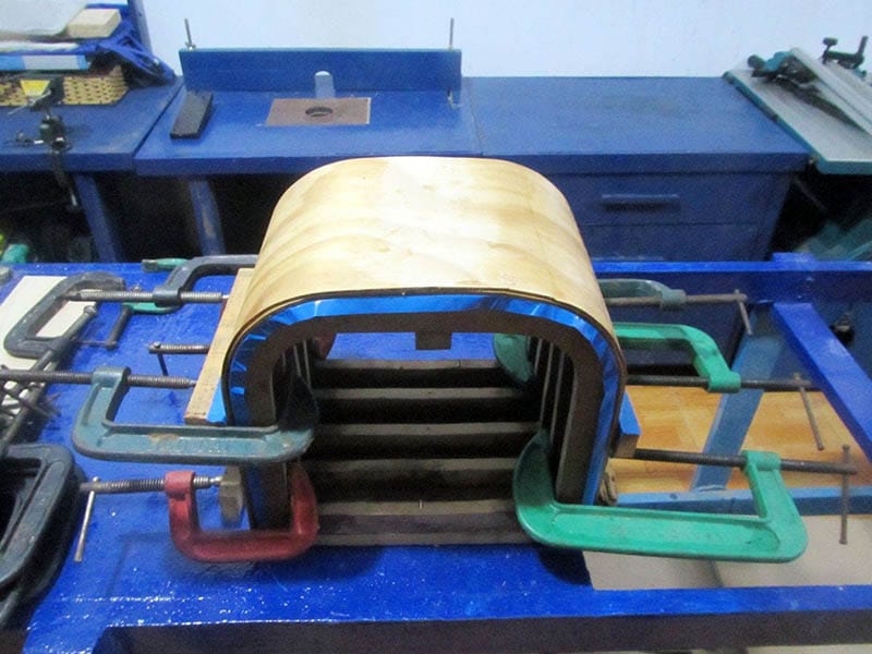
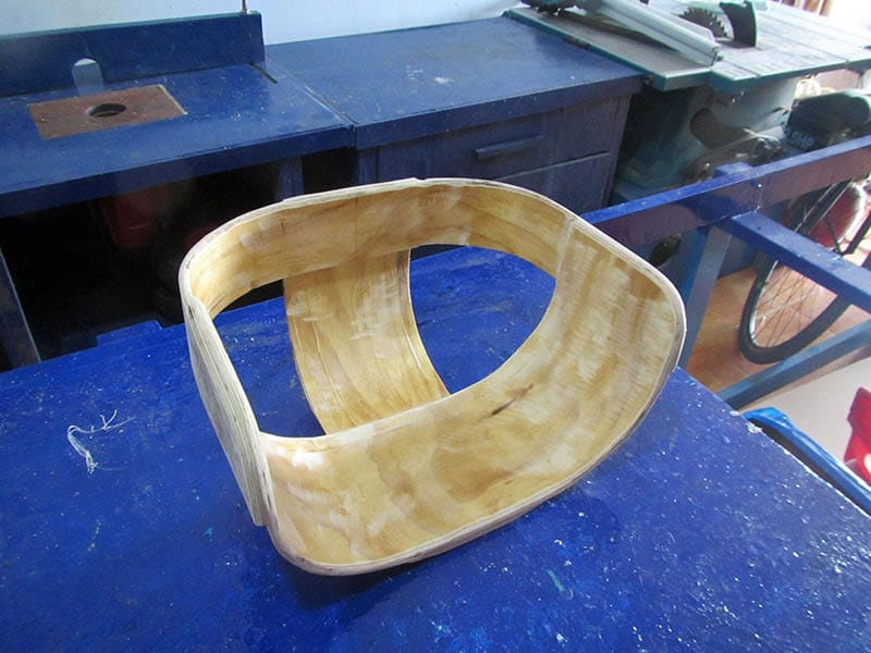
In parallel to cutting, jointing the bilges and forming up the hull and deck parts, I’m also making the cockpit coaming and hatches. They both use the same techniques of bending thin strips of plywood (2 layers of them) around a MDF frame to form the lips’ shape. Now that I have some much better – quality plywood sheets, which is not too easy to crack while bending into extreme curves, this enables me to construct the cockpit coaming and hatches in a much easier and convenient way.
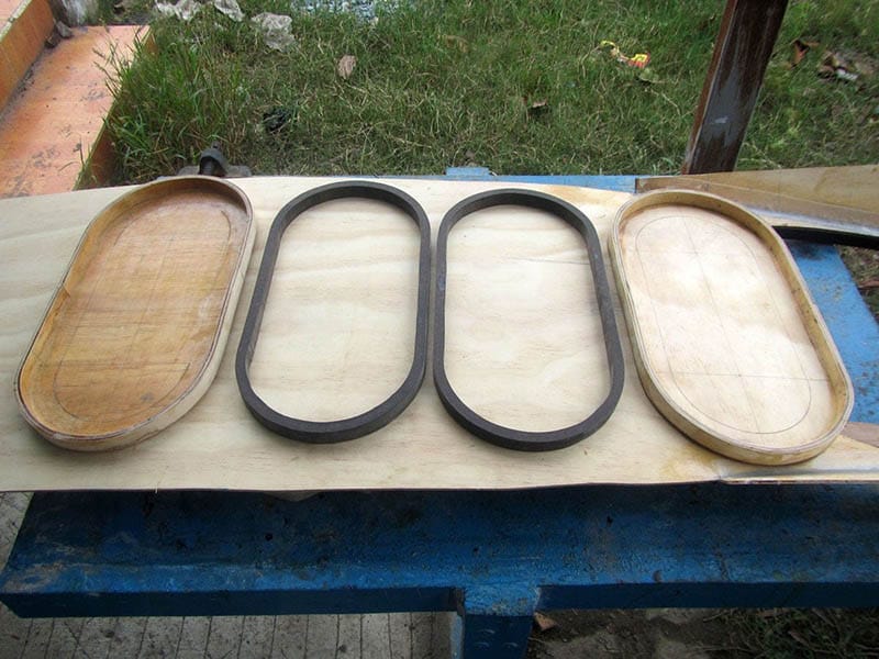
Both 2 hatches would be of the same shape and size, a “rectangular” with 2 circular ends (or could be called: a rounded rectangular). The hatches’ lips and the coaming lips are built up from 2 layers of 4 mm plywood strips, glued together. The flexibility of the ply serves well to the building, the lips take up shape easily, and stay in that shape steadily. In all, they’re all simple really constructions. Special thing about the hatches this time is that they would have elastic silicone gaskets inside.
Recently, I’ve learnt about silicone molding, using 2 – parts silicone mixed together just like epoxy. So I would mold the gaskets specially to accommodate the hatches, and would describe that in another following post. Hatches’ waterproofness has long been a serious issue to me, hopefully, I could resolve it completely this time. An handy (last resort) trick could also be useful: cover a layer of (very thin) PE plastic over before closing the hatch, that would make it absolutely water – tight.
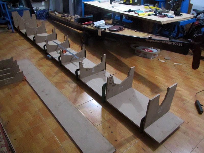
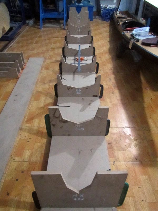
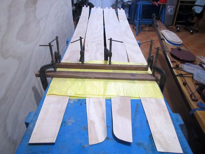
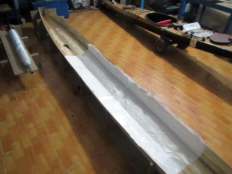
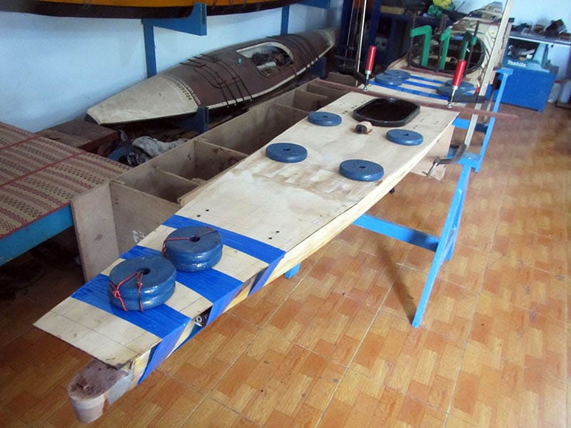
Itook great care in aligning a bilge’s parts, to make sure the final piece would come exactly to it designed shape, and to make sure the port and starboard bilges are identical, or else, the boat would have a twisted hull. All joints is slightly sanded, and applied a layer of glass on the internal side. Next come the job of putting everything together using a combination of fastening wires, super glue and duct tape. Having experiences from previous boat, I used very little steel wires this time.
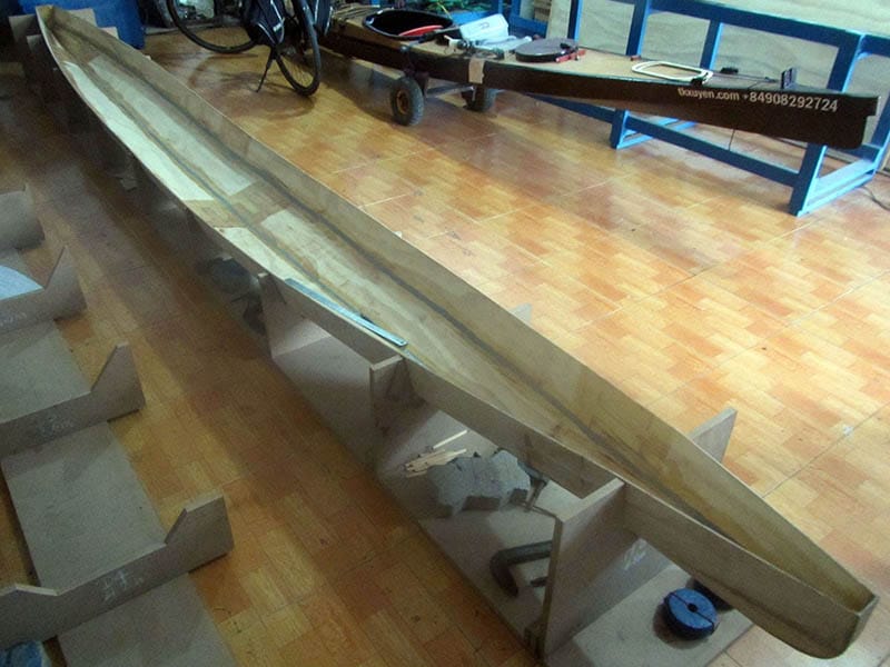
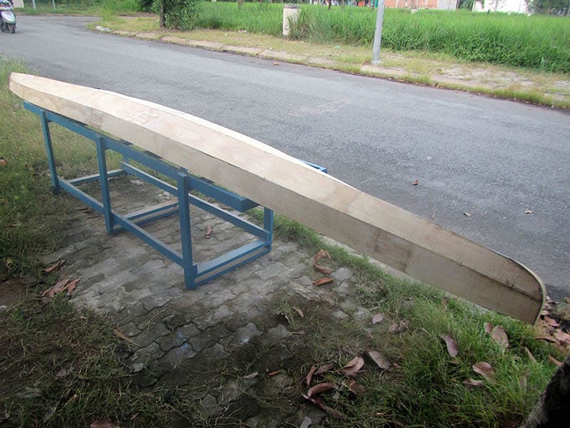
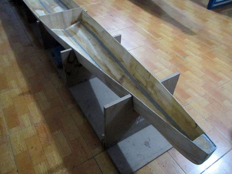
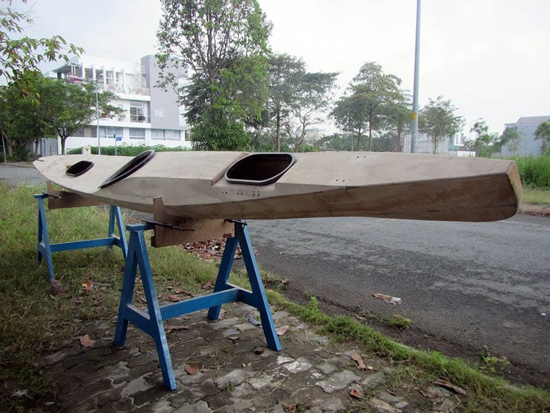
It’s so good to see the bilges fit naturally into their position, with minimum pressing, adjusting efforts. The tendency to take shape easily proves that you’ve all done right in the previous steps: measuring, drawing, cutting and jointing the biges. This is for the first time, you would have an initial impression, of how the boat would finally look like. The computer 3D renderings are too small to have a precise assessment, and of course, it’s always much more lively with a tangible object!
Looking at these two halves: hull and deck, having a senses of every details, it’s easier to arrange and schedule the next tasks. There’re so many jobs ahead: make and install the (recessed) hatches, hatches’ locks, install the cockpit coaming, rudder pedals and control lines, compass, the bilge pump, etc… and of course the whole complex electric & electronic system. Things should be better done this time, with the lessons learnt (tediously and expensively) from previous boat projects.
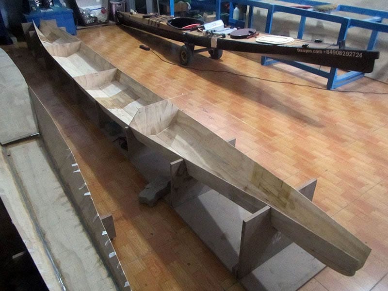
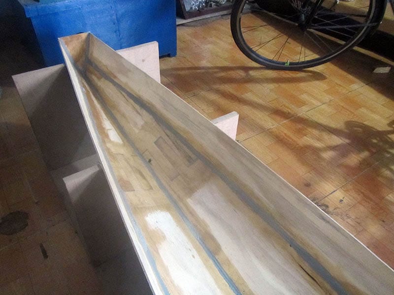
That’s the stitch part (of “stitch and glue”), or more precisely, most of it (since there’re still the bow and stern pieces to be put in, but that would be discussed later on), next come the gluing. First the seam lines are “primed” with epoxy (applied with a small brush), then filled with fillet (the tried – and – true 2 – parts epoxy putty 511 that I’ve been using extensively). The “gluing” part is a very time – consuming job, you have to meticulously fill the putty, which slowly flow down under its own weight.
So I have to apply the putty in 2 turns, first fill in just a small bit of them, wait for it to cure, then fill over the first layer another time. This is to ensure that the putty could form curved seam lines that would be easier to glassed later on. You can also mix small batches of putty, wait for about 30 minutes for it to cure partially, then apply it on the seams, the higher viscosity of the slightly – cured putty enables it to better keep its shape. In all, it’s a very time – consuming (and dirty) job!
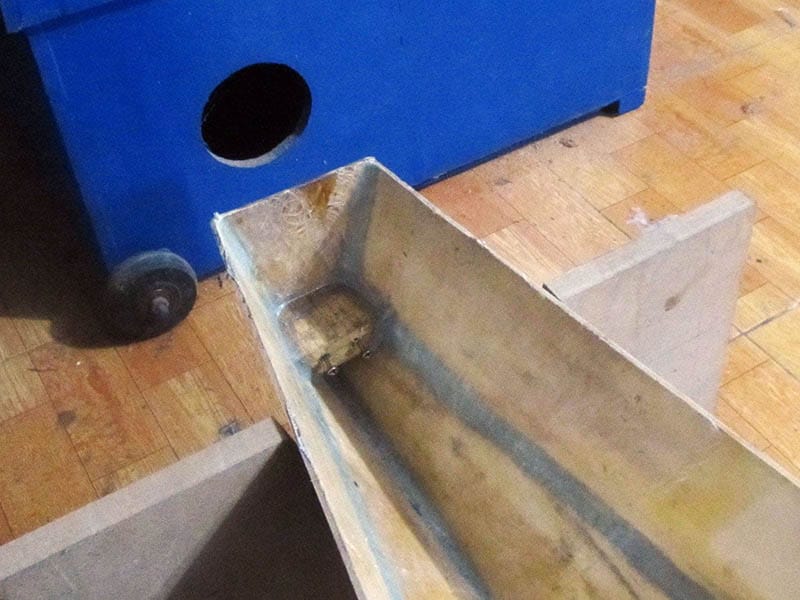
Next come in the bow and stern pieces. These small triangular plywood pieces need to be bended into curved shapes (see the 4th images below). I simply put them into boiled water for them to soften a bit, then slowly and carefully bend them with a pincer. The bow and stern parts are then temporarily fixed in place with hot glue and duct tape, then permanently glued with epoxy and fillet (putty). Now, the whole hull is rigidly glued in its internal side, similar job is applied to the deck part.
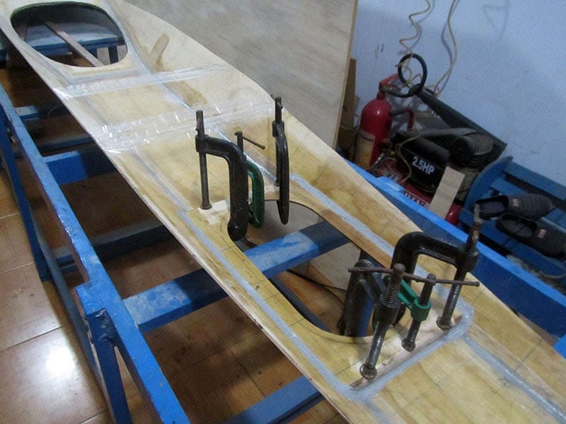
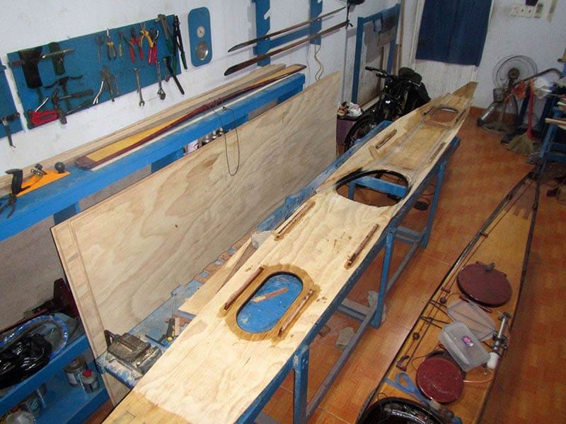
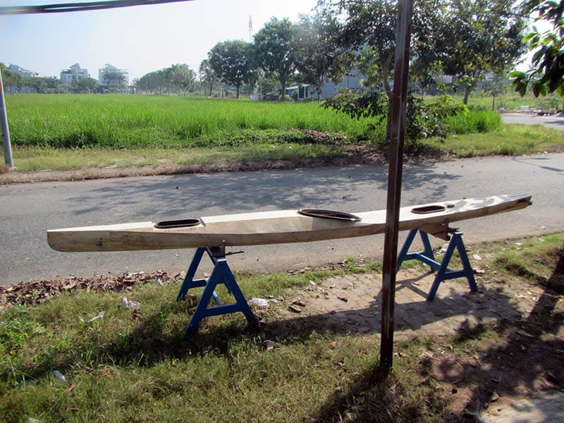
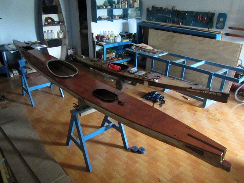
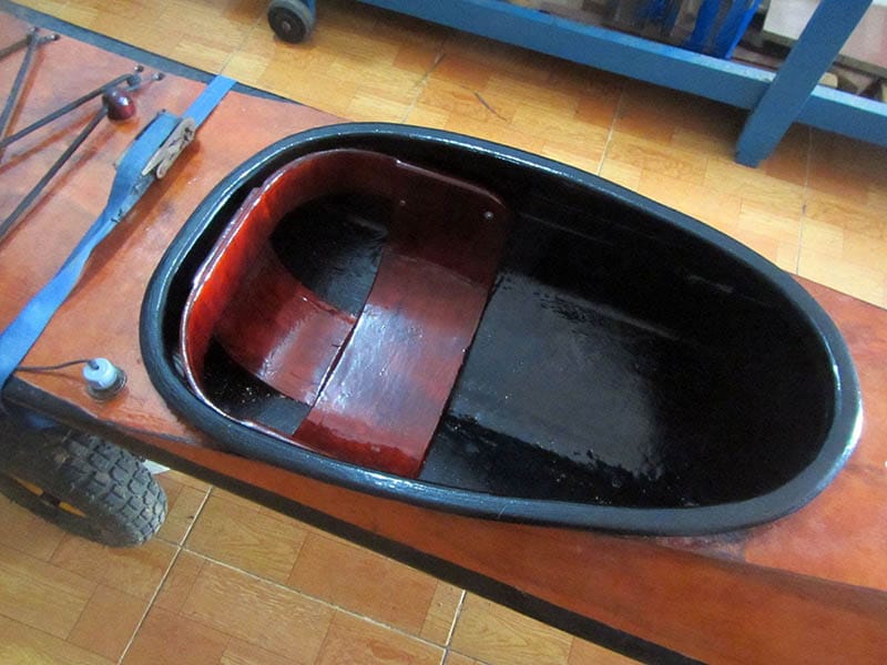
Hull and deck parts are basically stitched and glued, those two halves of a peanut shell. But that’s only a basic milestone, lots of jobs required still to make this shell functional. I continue to build the hatches and cockpit coaming, and various other accessories. 3rd image: the cockpit coaming glued in, stained with epoxy filled with black color pigment, later on, some layers of transparent PU paint would make the finish. While the cockpit is easy, it’s a bit more complicated for the hatches.
Both two hatches is of the same shape and size, for the sake of easy constructing (the hatches and their silicone gaskets). The forward hatch is built recessively into the deck, not only to keep a flushed, flat deck, but also simply because the hatch size is a few centimeters larger than the deck’s top, it needs to sink down to fit. It’s a bit tricky to build the recess, so I decide to get along with a rectangular approach (it’s much easier to build, though a circular one would certainly looks much better).
The aft hatch raises about 1 inch from the deck, not too high to interfere with reentry climb – in actions. I would try a new idea for hatch locking, something that’s easy to operate and tight enough (offer some pressure down) to secure the hatches in places and help with waterproofness. Hatches and hatch locks have been causing my headache for long, but it seems, the best solution is indeed simple, I wonder why my common – sense has not come up with it in the first place.
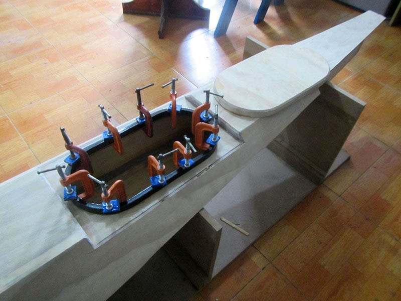
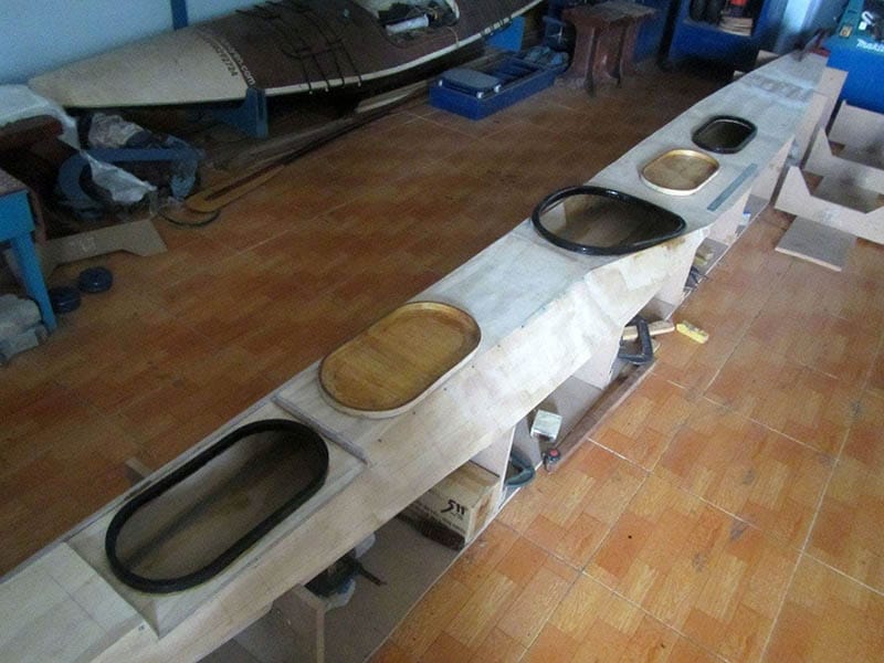
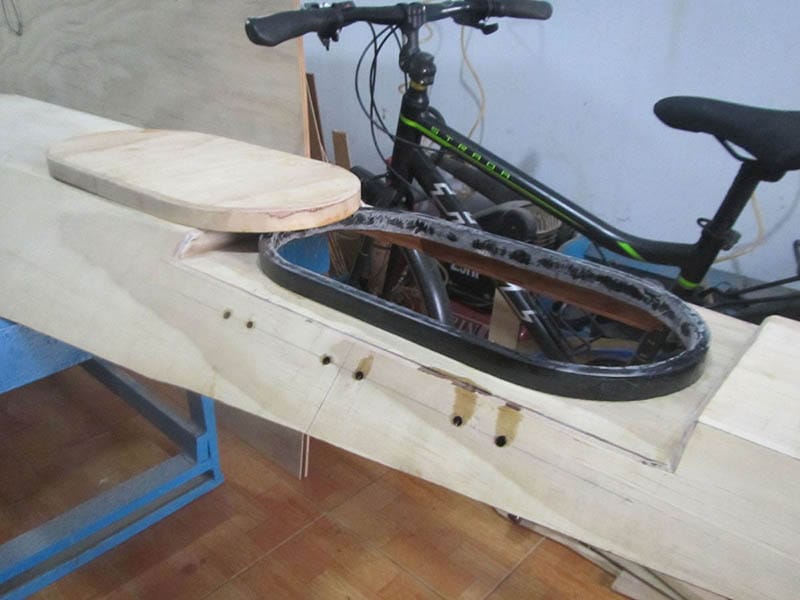
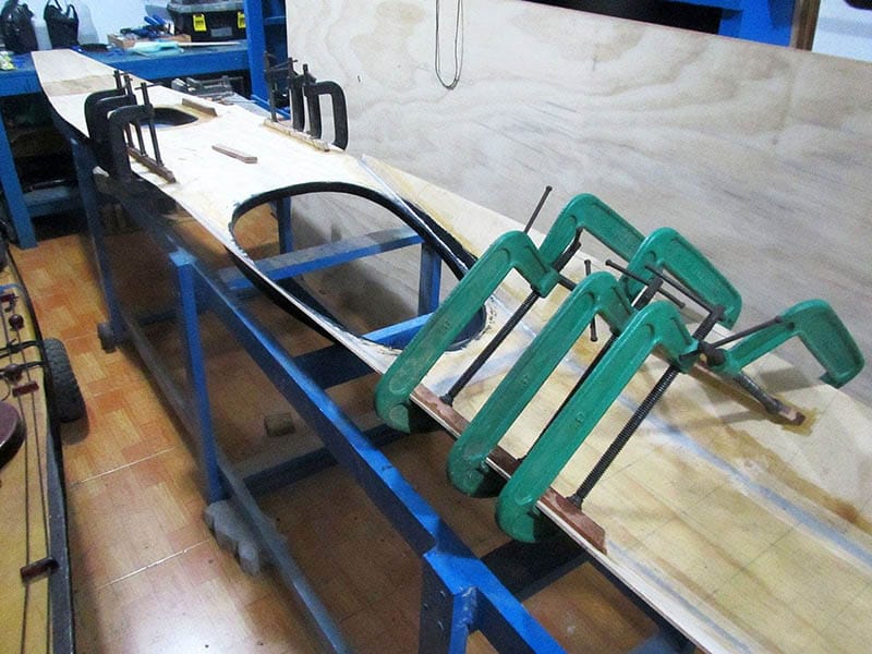
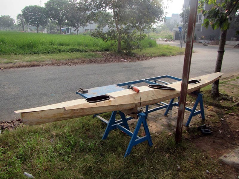
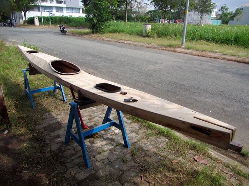
Continue working on hatches. First image: the completed two hatches (still without the gaskets inside) with the hatch rings (rounded rectangle in shape, cut from a sheet of MDF and strengthen with quite a lot of epoxy). Second image: the recessed (flush deck) forward hatch, the deck is cut 1 inch down, and about 45 cm along the length to get a wider space to install the hatch. This part of the deck is quite weak, and need to be reinforced with some putty and fiberglass inside.
The hatches’ size look a bit small, 18 x 38 cm internal (cut out) side, but that’s sufficient to let many things through, e.g: water bottles or the tent bag, most objects are of long and narrow shapes. I intentionally try to keep the hatch size small as possible, to help with waterproofness. Third image: gluing the forward hatch ring onto the deck, the recessed base is about 1 inch lower, so that when the nearby hatch (seen on the right) is closed on, it would flush with the rest of the deck surface.
The same is done with the rear hatch (not shown here, but you can see it with the image album link on the left). Good thing is that the hatches and their rings fit together really well. Next I would round the internal side edge of the hatches’ ring a bit, cover them with a layer of glass. Completion to the very details in required indeed, in the last trip, I accidentally damaged one of my clothing bag, trying to pull it out of the cramped storage compartment over this sharp, unrounded edge.
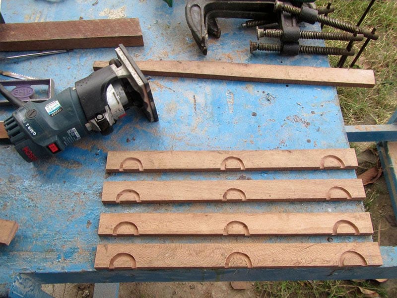
Next came the hatch locks, each hatch is hold down by 3 belt – locks, similar to those usually found on your backpacks, very secured and easy to lock / unlock. But that would be later on, for now, the locks’ anchor points need to be built and installed. There are many of them (a total of 30), as the anchor points are not only used for holding the hatch lids down, but also for other lashing bungee cords, and they are built exactly as in my Serene – 1 & 2 previous kayaks, a tried and true technique.
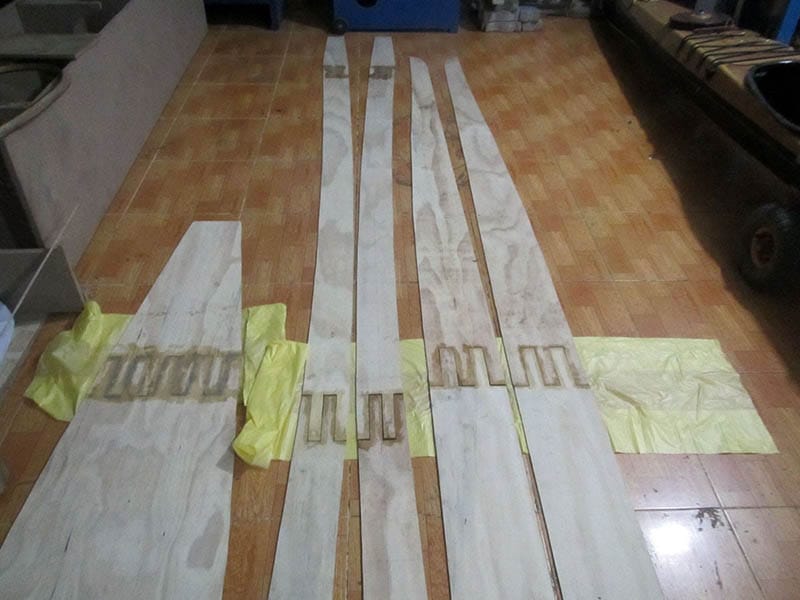
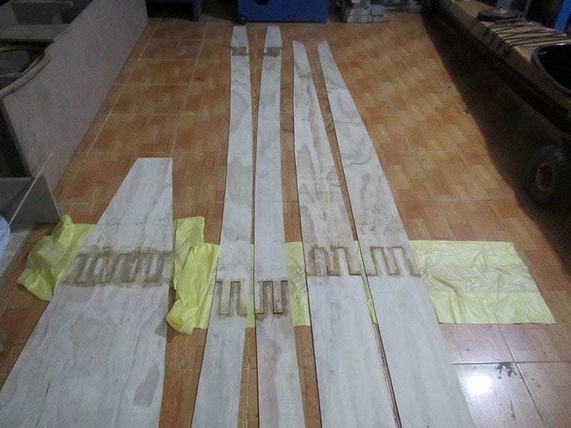
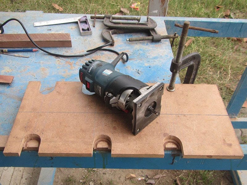
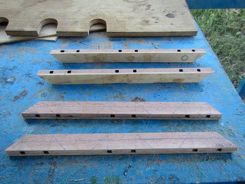
A line would (from the external side), go though the “half – circle tunnel” drilled inside the wooden blocks and loop back to the external side of the hull, forming very strong holding points for various lashing lines. I made two MDF templates and cut the grooves with my very handy Bosch router (first image), a set of three anchor points is placed on one same wooden bar (second image), and install as a whole (fourth image) for the ease of installation, just gluing the wooden bars to the deck.
The deck doesn’t receive a layer of fiberglass throughout, it is only reinforced at critical positions: around the cockpit, around the hatches, or along the seam lines, to help keeping the final weight low. But for an “expeditional boat”, weight is not the primary concern, the boat need to have some “mass” to withstand considerable amount of abuse in long paddling trips. I would expect around 20 kg finally! It’s bad that I’d seen the hull flexing a bit under heavy loads with my Serene – 2 kayak!

Deck works continue… installing the anchor points, 12 for the 2 hatches, and another 12 for the lashing bungee cords, and additional 6 at various places along the deck, quite a lot of work. But there’re many other “unnamed” jobs related to the deck still: beveling the cockpit and hatches joints, glassing the cockpit joint, install the bulkhead… I also switch back and forth between the deck and the hull: glassing the hull’s internal seam lines, gluing the wooden blocks at bow and stern, etc…
First image: the anchor points to hold down the forward hatch, 6 pairs of 6 mm holes (both on port and starboard sides) are used to mount the 6 loops of 4 mm paracord, which in turn are used to secure the belt locks. Second image: various anchor points are placed along the deck, some used for the hatches, some used for bungee cords, and some are just “reserved”, those are not readily in use, but provided for lashing things down on to the deck should the need arise.
Third image: wooden block glued to the bow, later a hole would be drilled through to run the kayak’s pulling line. Fourth image: another wooden block glued at the stern, note the two 5 cm screws, to fasten and reinforce the rudder post (would be installed later). The rudder post is another wooden block glued on the external side of the stern, rudder, rudder post, rudder control lines and control pedals, and the “new” rudder box are important issues that would be covered in next posts.
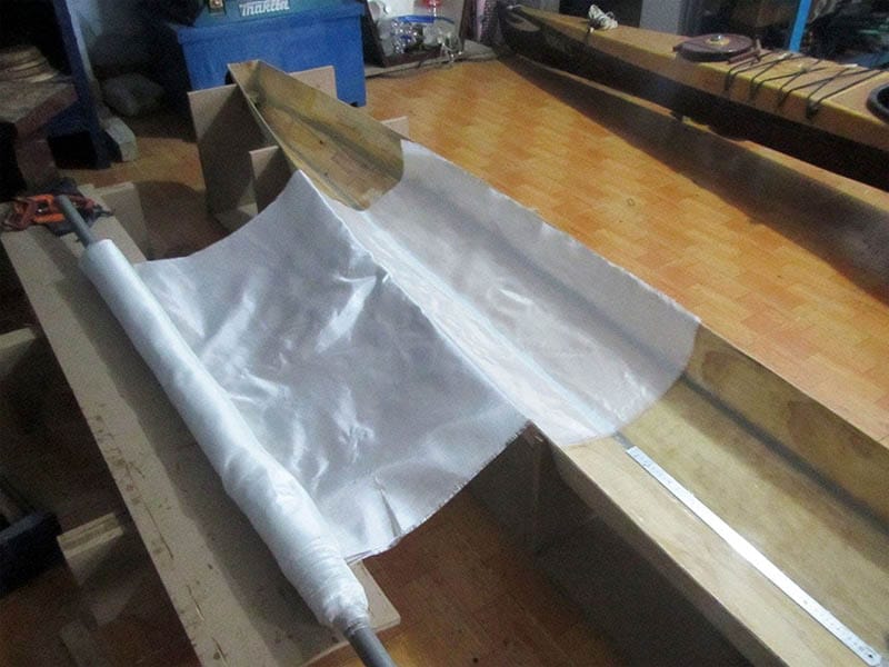
Purchased a new roll of 6 oz fiberglass, also “plain weave” like that was used in my previous boats. Surprisingly, the 2 kinds of fiberglass cloth, both 6 oz and plain weave, are not really the same, the later cloth has finer and denser fiber, it’s slightly heavier, a bit harder to wrap around and it absorbs more epoxy. It’s now time for some glassing, the hull receive a layer throughout its internal side, while the deck is only reinforced at places: around the forward hatch and around cockpit.
In my calculation, glassing adds, on the average, about 0.4 kg per square meter of surface (the glass mass itself plus the epoxy). So, glassing both inside and outside of the hull would add about 2 kg into the boat weight. That’s not really a big issue, as long as the glassing work is done properly, avoid using too much epoxy and keep weight in control. Sometimes, you need to step back and watch for everything you’d done during the past times. It seems that with 5 kayaks, all stitch & glue…
I’m becoming what they usually call: a prisoner of one own experiences
, having designed and built several boats again and again using the same methods and techniques. While that’s somewhat true, in each boat, I’ve been trying to incorporate new things, new design ideas, new techniques, new accessories… My thirst for “the perfect kayak” has not been wholly quenched yet! And that “great journey” has not been done yet, lots of things waiting ahead to be full – filled, to be accomplished!

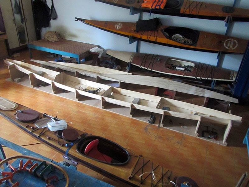
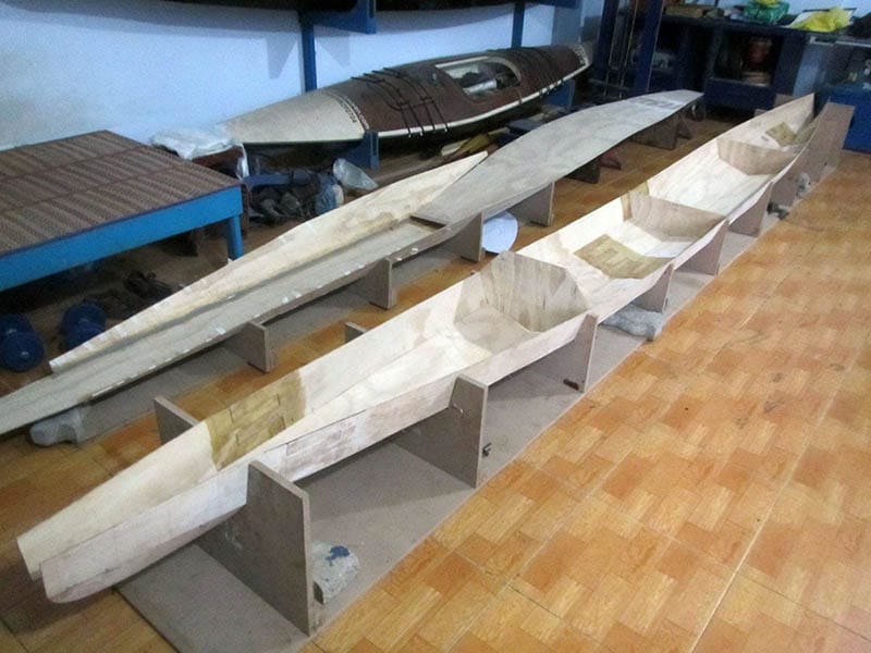
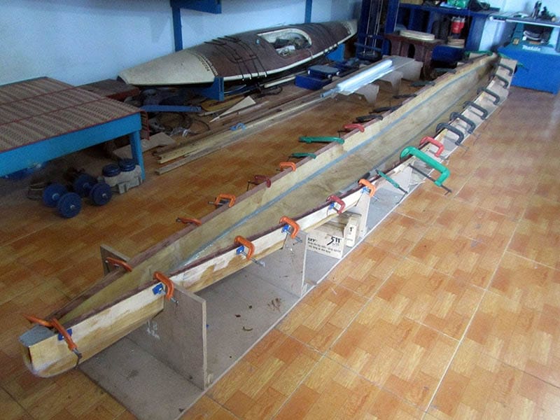
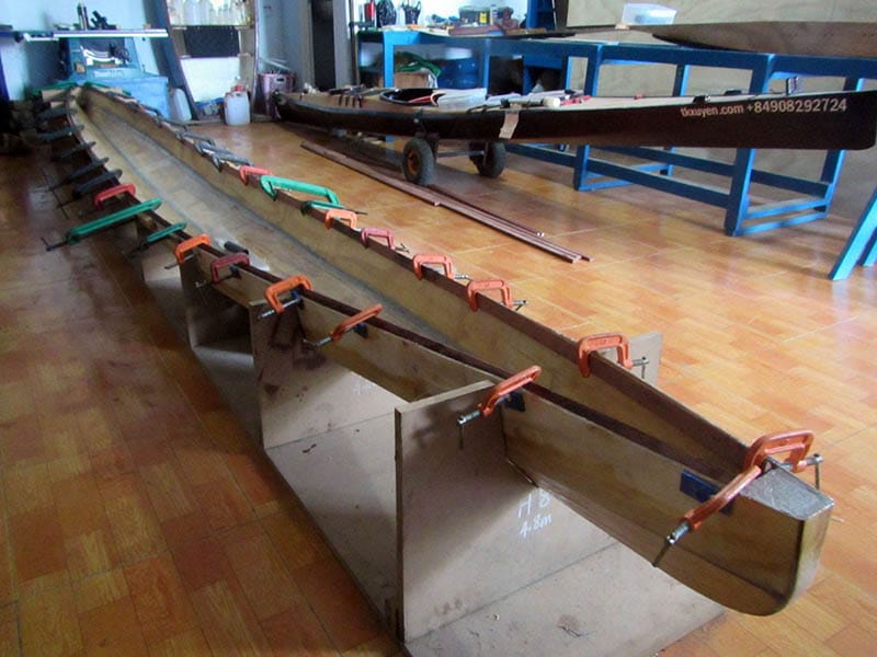
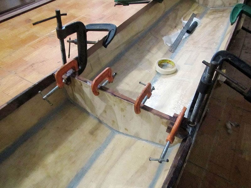
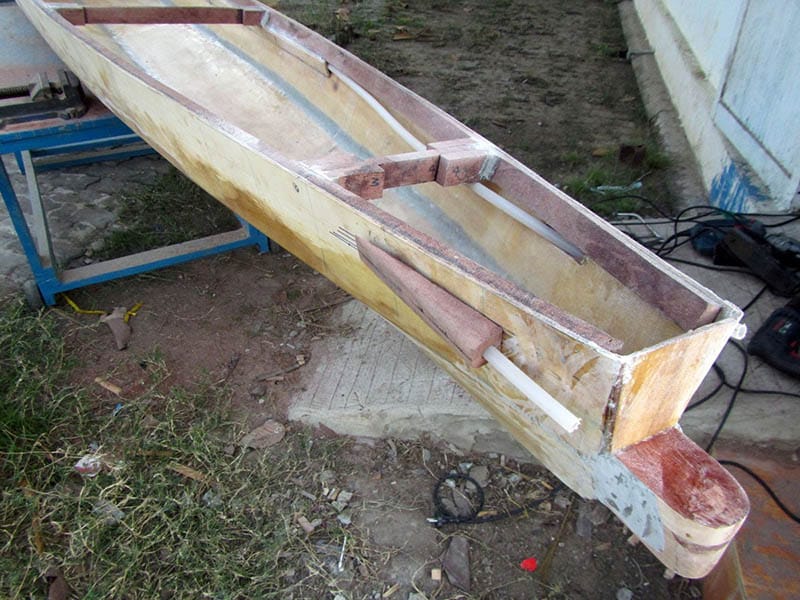
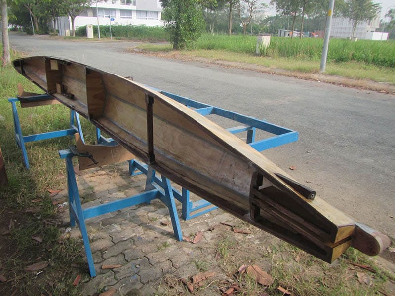
Now go in the gunwales, bulkheads and thwarts, which make the hull looks more “full fledged”… Indeed, those gunwales, bulkheads and thwarts would transform the hull into a structure, which is much more stiff. Gunwales are thin strips of wood, 1.5 x 3 cm in cross section. I cut all those wooden strips with my small Makita table saw, which is extremely helpful for a wide range of different jobs, especially because it cuts are flat and straight, unlike those made with a hand held jig saw.
The more I use it, the more I discover new techniques and tricks to get some jobs done. Also with the Makita table saw, I bevelled the gunwales, diagonal cuts at 45 degrees along the forward parts of the gunwales. I would adjust those bevelled edges along the boat length later, to better match the hull versus the deck. Now having a total of 32 clamps of different types, I’m able to install the two gunwales, port and starboard at the same time, not one after another like before.
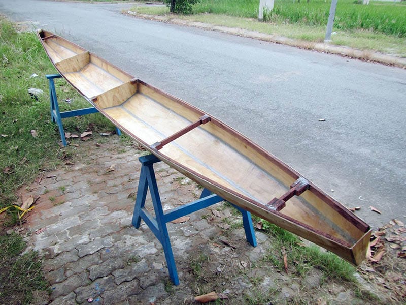
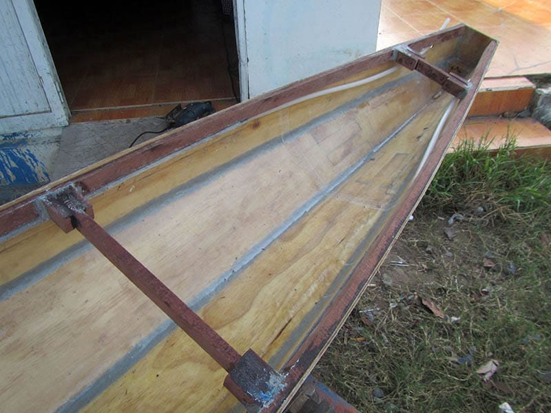
There’re two bulkheads compartmentalizing the kayak into 3 sections, and 3 additional thwarts near the two ends that would help transforming all into a rigid structure. All is glued in places, then reinforced with small 4 cm screws connecting them to the gunwales. Then putty – fill the bulkheads to secure them to the hull, then a layer of glass over on the cockpit side since that’s where they could be potentially exposed to water. Still some more jobs need to be done to complete the hull!
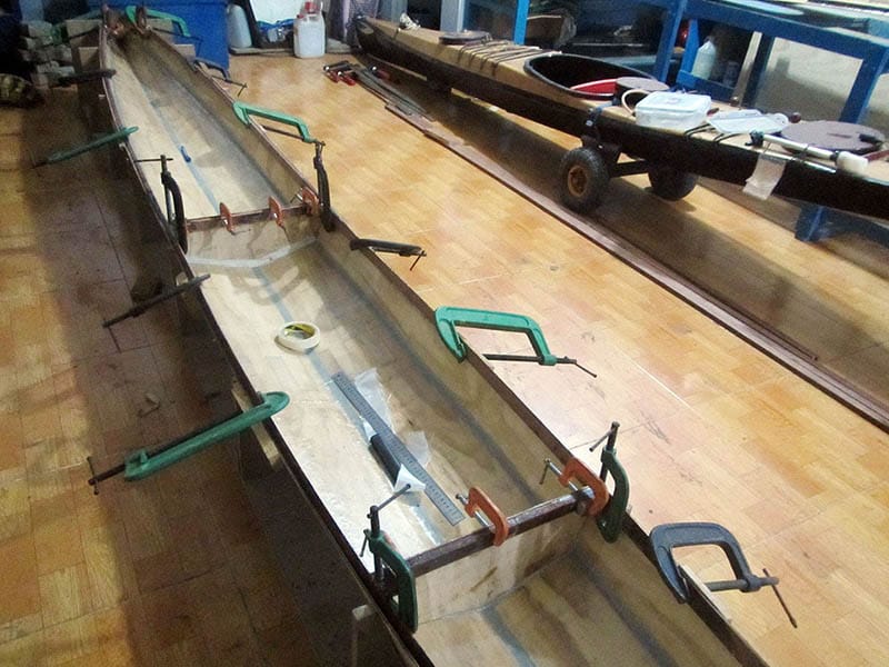
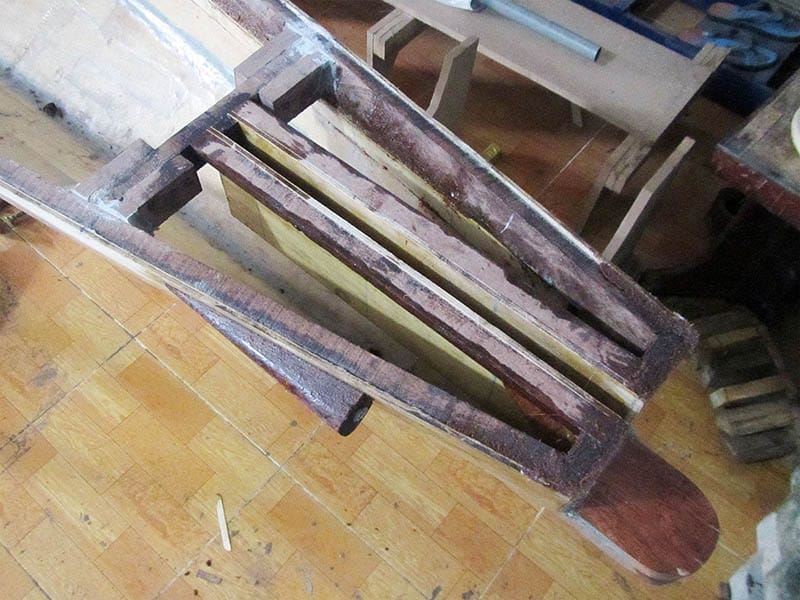
Hull is rigid like a walnut shell now, I took it out for a slight sanding on the external side before applying extra layers of glass at bow and stern, the two ends that would withstand quite some abuse when landing on unfavorable shores. Then I install the rudder post, a piece of wood that protrudes the flat stern about 7 cm, glued, screwed, filled with putty and then finally two layers of glass. Lots of extra reinforcement for this rudder post, a lamination of 3 different layers of wood.
I carefully choose different types of wood, with different wood grains to make up this simple rudder post. The grains that run in different directions would ensure that this wooden block would be more resilient to forces from various “angles of attack”. Then I install the rudder control tubes, plastic tubes 10 mm in external diameter (6 mm internally), quite large indeed. The large tubes is, for later, I could easily try various types of rudder control cable, to see which works best.
The tubes run just below, and along the gunwales, through the bulkhead, fixed in place using epoxy putty and small strips of plywood. A lesson learnt from my previous boat: fix the tube positions, don’t let them run loose, slightly different port and starboard tubes would result into different tensions on the control lines, or an awkward rudder pedaling control effect. The tubes exit the hull through small slots cut very near to the stern, protected outside by small blocks of wood.
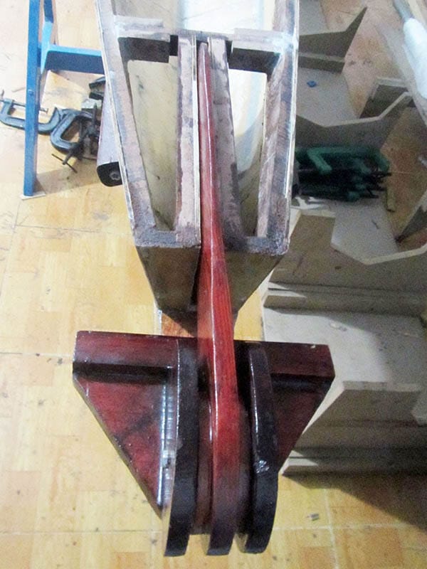
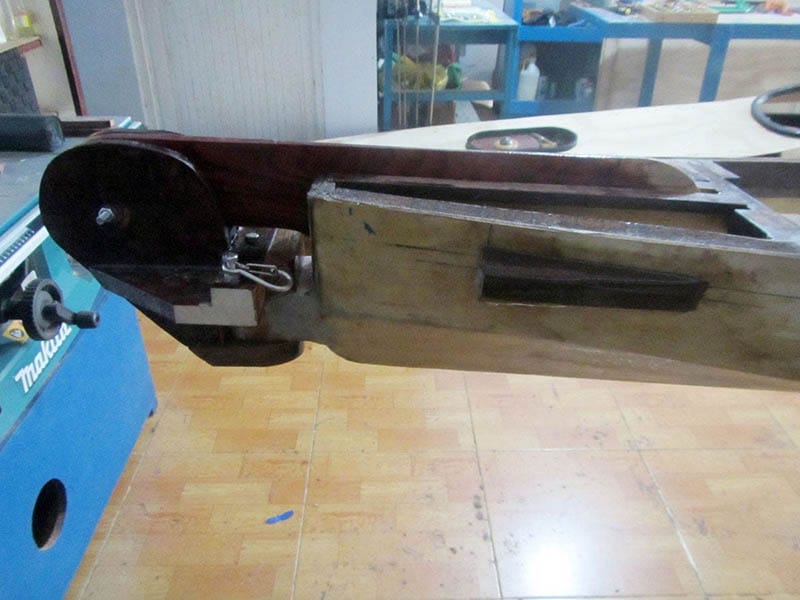
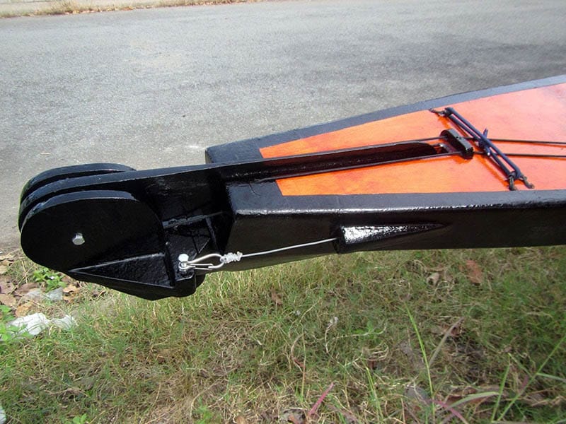
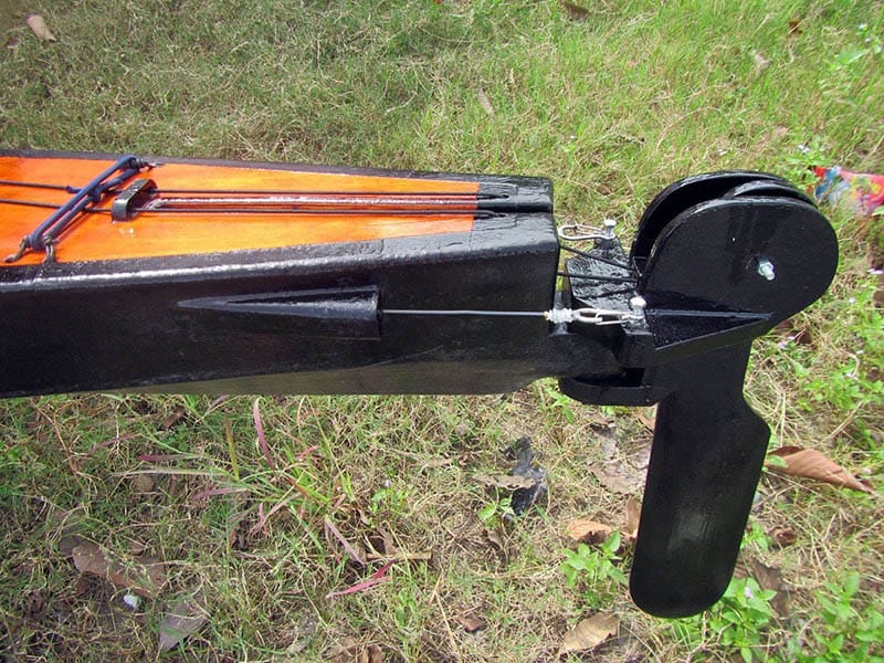
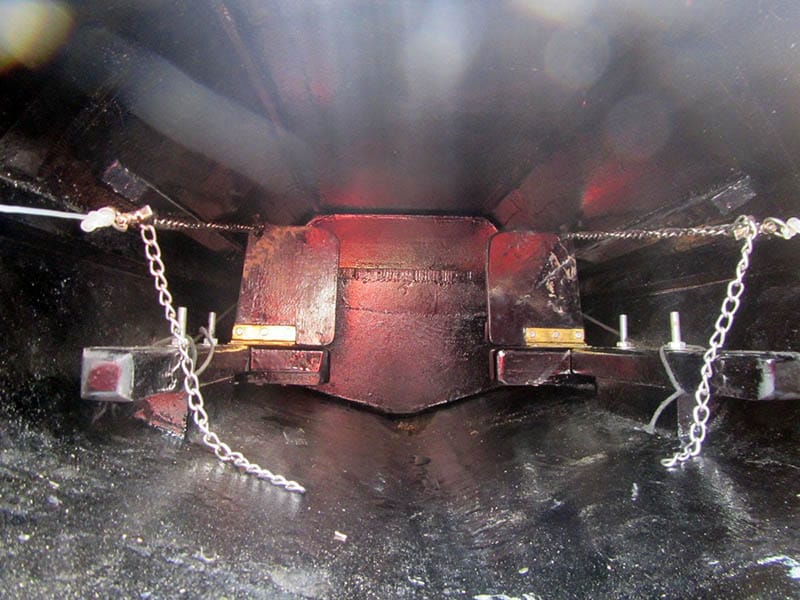
Next came the rudder box, an interesting idea that I’ve come up with lately. First, when not in use, the rudder would be retracted completely inside the rudder box (and so inside the hull), it would be safer, tidier when transporting, moving the boat around. Second, and more importantly, the rudder box allows mounting the rudder in a lower position, which enables a smaller rudder blade. From the design phase, when drawing a hull with lots of overall rocker (the keel line has quite some curvature)…
I saw that bottom of the stern would barely touch water when the kayak is at full load, hence, it’s good to mount the rudder lower down, about 10 cm lower compare to my previous boat. So I would just reuse my previous rudder with more steering effect. Lessons learnt from Serene – 2 showed me that I need a more responsive rudder, so everything, from the rudder post to the control pedals must be redesigned, shorter “rotating arms” for the rudder, and smaller “moving distances” for the pedals.
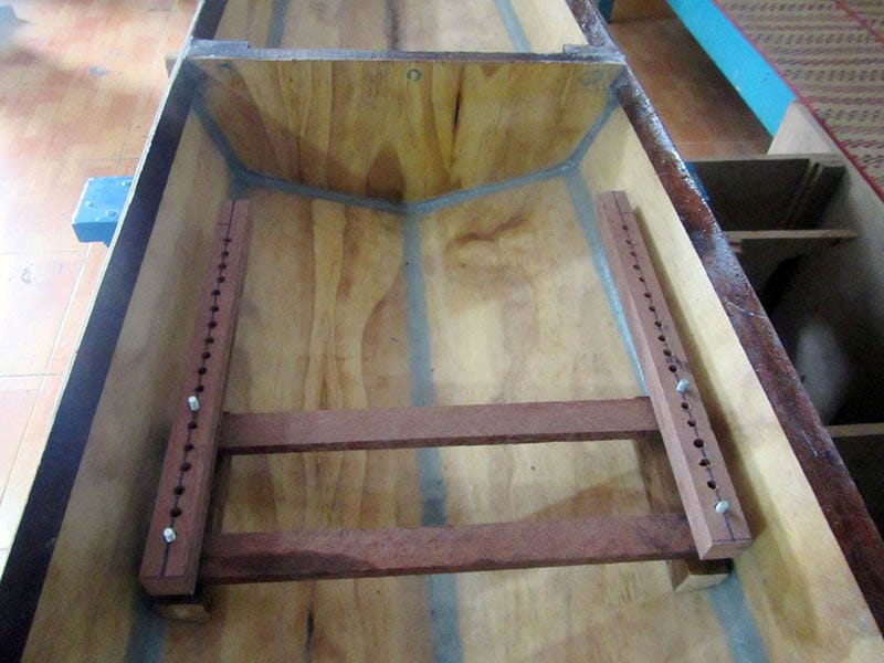
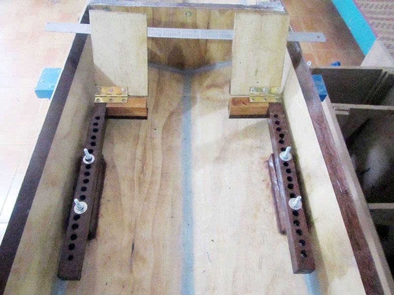
For this Serene – 3, I would make the seat position fixed, so the rudder pedals must be adjustable, back and forth about 12 ~ 15 cm. Of course there would be only one paddler for this boat, that’s me, but an adjustable rudder pedals is desirable anyhow, though it’s not very frequently needed. I choose a pedal layout that would let me stretch and relax my legs and feet. Not a surfing boat, rudder is for some slight course adjustment only, I don’t have to rest my feet on the pedals most of the time.
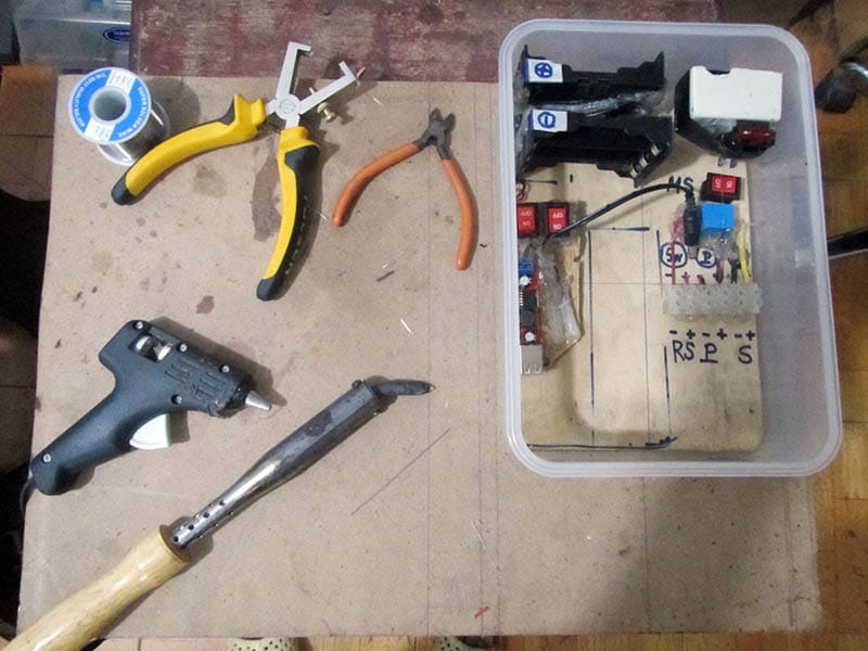
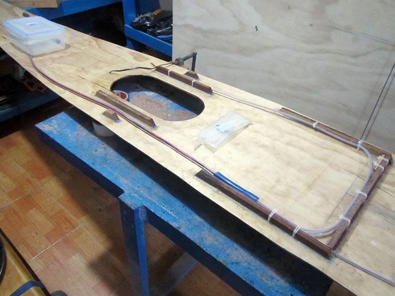
After lots of considerations, I made up my mind to implement the electrics – electronics system of this Serene – 3 kayak as simple as possible. There would be no built – in compass and nav lights. Only a set of six 18650 Li-ion battery cells charged from the solar panel, and a reed switch to activate the bilge pump. That would reduce the electrics wiring hassle to minimum, simplify the installation quite a lot. Of course, the compass still needs lighting to be used at night, and the nav light too.
Looking back on the electric, electronics part of Serene – 2, I’ve seen that I’d over – engineered quite a lot, things should be simpler. The compass and nav lights would now be a single hand – held torch, powered by rechargeable AA batteries, I would detail this “solution” in later posts. And the electrics components should be decoupled to facilitate repairing, upgrading. All the wiring runs inside plastic tubes (as additional protection) and can be pulled out of the hull for repair when needed.
So basically, the system composes mainly of Li-ion cells that would have 2 duties: power the bilge pump & the charger that would replenish some AA batteries. The AA batteries would be then used to power the Garmin and the light torch. Also in the waterproof electric box is the USB charger, which could be used for a variety of electronic devices. And I believe most if not all chargers could be modified to use either the 5V (USB) or the 12V (Li-ion) source, would try to check (prove) it later on.
Lots of “unnamed” jobs need to be done: slightly modify the rudder (shorten its rotating arms, slightly shorten then rudder blade by 1 cm, add the carabiners for simpler rudder line attachment…), prepare the bilge pump mount, double check to make sure if all electrical wiring works (things made easy with a multimeter: voltage, current, resistence) etc… Then I carefully check the bevel along the gunwales, to make sure the hull and deck would match, adjusting their slopes with an angle grinder.
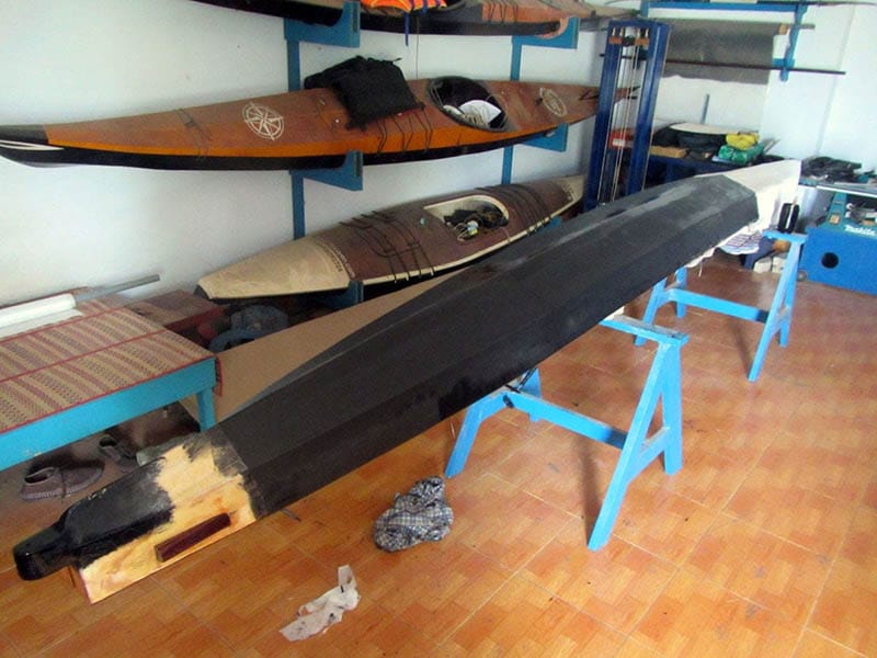
Then, let joint the two halves of the peanut shell, it’s always a really good feeling when your boat initially is turned into its final shape! I ran out of the very handy and useful 511 putty, and lazy going out to buy a new batch, I fall back to working with wood flour fillet, though wood flour is not as good as the very fine grain powder of 511. Priming the joint with epoxy and some fillet, press the two halves together with weights, duct tapes, clamps, fastening belts… anything that’s convenient.
The deck has not come to its final shape yet since it’s cut oversized in order to have some fault tolerance. Next is the job of trimming the deck to the desired shape, then reinforce the hull – deck joint with some fillet at places, there’re still some small gaps between them that need to be filled. If done properly, it should make air tight (and water tight) compartments inside the hull. Later a layer of hull glassing would overlap about an inch onto the deck, to help securing the joint further.
Deck and hull jointed, for almost the entire length, almost no additional glueing is needed, almost a perfect fit, no light seen through. Only around the cockpit, the widest part of the boat, needs some fillet to fill some small gaps. However, as a precaution, I applied some little additional fillet at places along the gunwales to make sure the joint is really secured. Now trimming the deck to match the hull, cut the slot on top of the rudder box, round the seam lines to facilitate glassing later.
Next, the whole hull and deck receive some sanding to smoothen out their surfaces, erase all the pencil and sketch pen marks. Those sketch pens offer very good indications, though they’re a bit hard to be erased off the plywood. Sanding is just a slow and dirty job, and it’s very itchy. The ugliest part of S & G boat building is sanding on fiberglass, it produces dust, which is essentially just tiny particles of silica sand, and those are extremely itchy, I have to take a bath 2, 3 times after the work.
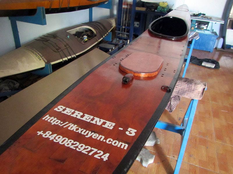
Over the time, I devised a trick to cope with this: rub your exposed body parts with some mineral oil (e.g Johnson’s baby) before doing the sanding job, then taking a bath after would remove those hateful dust easier. This time, I do the sanding job more carefully, one at 100 grit and another at 120 grit before applying the wood staining. This time, I decided to go with a less vibrant color scheme, light brownish for the deck and black for the hull, unlike previous boats with bright yellowish tone.
Deck is stained with brownish wooden color, a color pigment is mixed with thinned epoxy and brushed over its surface. Epoxy is thinned for two purposes: first, to lower its viscosity so that the mixture flows easier and make a more even surface, second is for the epoxy to be absorbed into the deck, since there’s no glassing for deck, better to add some water resistance capability to the exposed plywood. This has always been my method of treating plywood if there’s no glassing.
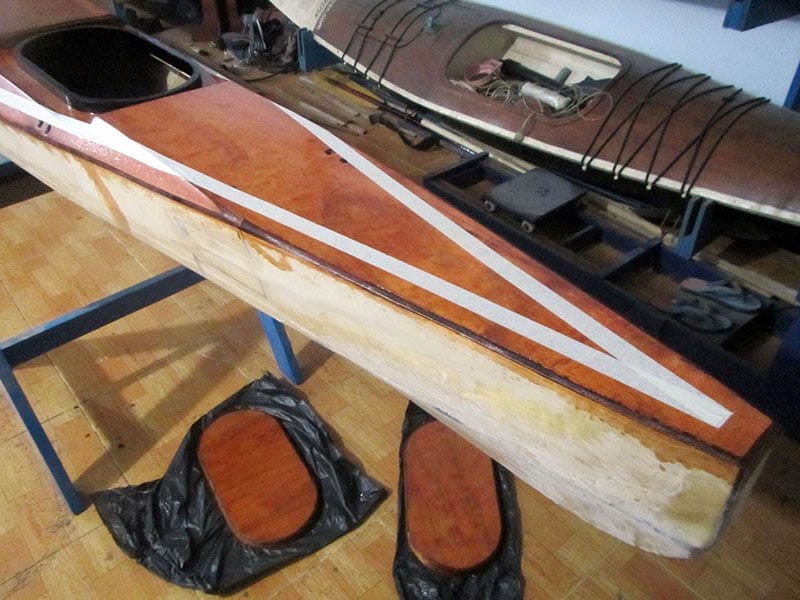
Next is to glass the bottom, this gonna be a quite heavy kayak (estimated to be approximately around 25 kg) since I’d decided to glass both the internal and external side of the hull, while the deck only receives some glass reinforcement on the internal side. I run duct tapes along the deck (third image) to mask the margin for glassing, two layers of duct tapes to prevent the blackened epoxy to spill over the deck. One very annoying thing with every duct tapes I used is that no matter how I try…
Epoxy still leaks a bit under the duct tapes, and the border line between hull and deck would become blurry. I used a trick to overcome this problem, after sticking the tapes, I brush a very thin layer of transparent PU over them, cured paint would prevent epoxy from leaking through while still enable pilling off the tapes. Fourth image: glassing the bottom, epoxy is mixed with a deep black color pigment, almost jet – black. Later, several layers of transparent PU would make the final finish.
One more lesson learnt: we can thin the epoxy when glassing too, sometimes the epoxy has such high viscosity (e.g epoxy from the bottom of the container) that it’s a bit hard to wet out the fiberglass, so I added some xylene solvent (less than 1/4 by weight), so that the glassing could go on easier, and the curing time is also prolonged, an important factor in hot tropical weather. Don’t worry about not having enough epoxy inside the fiber, cause we would usually have another fill coat anyhow.
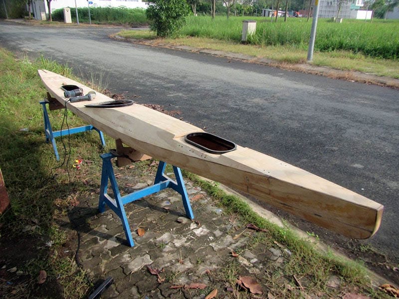
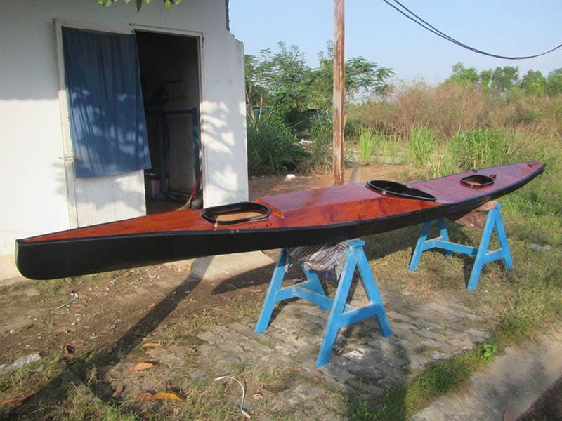
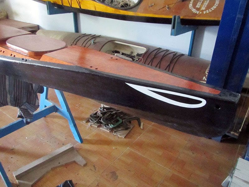
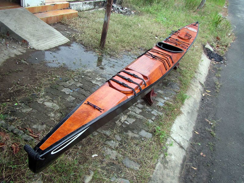
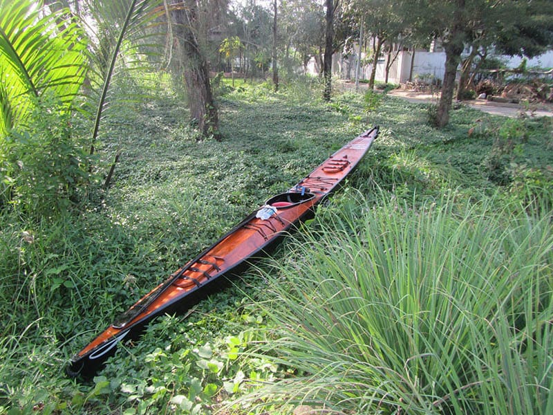
Hull glassed, 1st image: trim the glass with a small scalpel and peel off the excess. Next, I put the fill coat on until no woven fabric is clearly visible, then slightly sanded the whole bottom. Then I sticked the white vinyl decals for the boat’s eyes and information (3rd and 4th images). Next, I painted the deck with 2 layers of transparent PU paint, and the hull with 3 layers. I ran out of PU thinner (butyl acetate) on the way, so I used acetone instead, it’s also a good solvent for thinning PU paint.
After 2 layers of paint on the hull, I slightly sanded it one more time, before applying the final coat. Well, I’m not particularly good at finishing, and like all my boats, all finish is just “barely – good – enough”, not a “very – fancy” look anyhow. But it’s important to have an even, smooth and thick – enough coating to protect the epoxy from UV and other abuses, the “2K” PU paint I used forms up a very hard protection really. In total, I used roughly about 1.2 kg of paint for the whole boat.
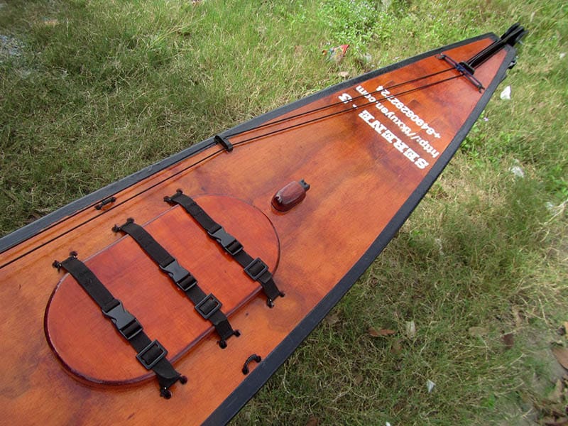
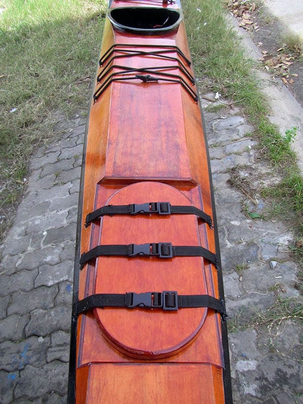
First image: the aft deck hatch, secured by 3 belt locks. These locks are usually found on your backpacks, and while they are a bit cumbersome to install, they offer quite some holding power and downward pressure, which is essential for the silicone gaskets inside the hatches’ lids to properly work (would mention about those gaskets in the next post). Similar locking for the forward hatch (2nd image). There’re 3 locks per hatch, so if one failed, the other two could still full – fill their duty.
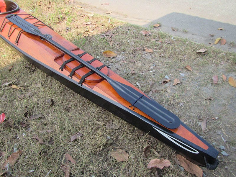
Next, I installed the rudder pedals and control lines. 3rd image: the rudder in retracted position, 4th image: the rudder in its working position. Thank to the lessons learnt with my previous boat, I redesigned, rearranged every details so that the rudder actions now is very light, smooth, and balanced: kick the pedals lightly and the rudder would follow, release a pedal and the rudder would come back to its neutral position. All control lines tension could easily be adjusted from within the cockpit.
I lubricated with silicone grease all the moving parts of the rudder system, the pivoting points, the lines and pedals, and everything became much smoother. I’m very happy with the overall working of the rudder, though this is still in – dock testing, let see how they would behave while on water. Can’t wait for water trial yet, as there’re still much things to be completed, the bilge pump, the electric box, the hatches’ gaskets, the seat, cart, and a new pair of paddles, etc… still many jobs ahead.
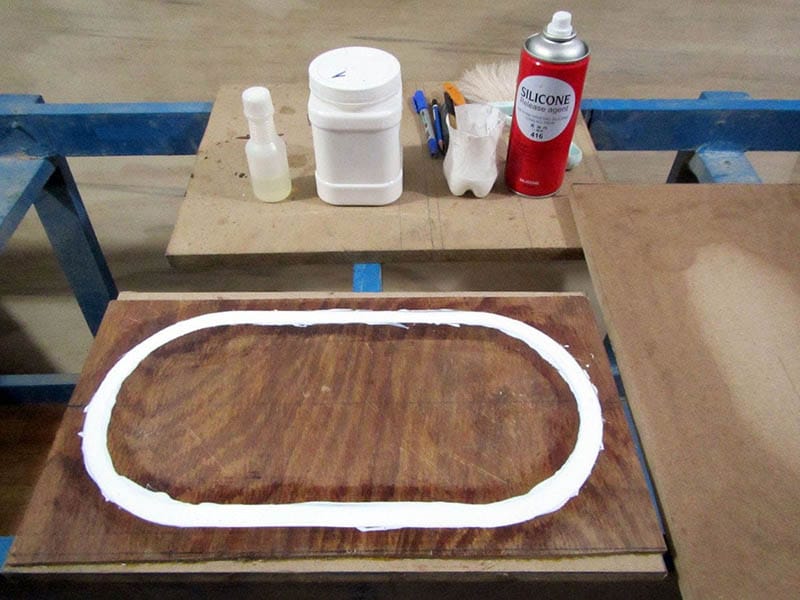
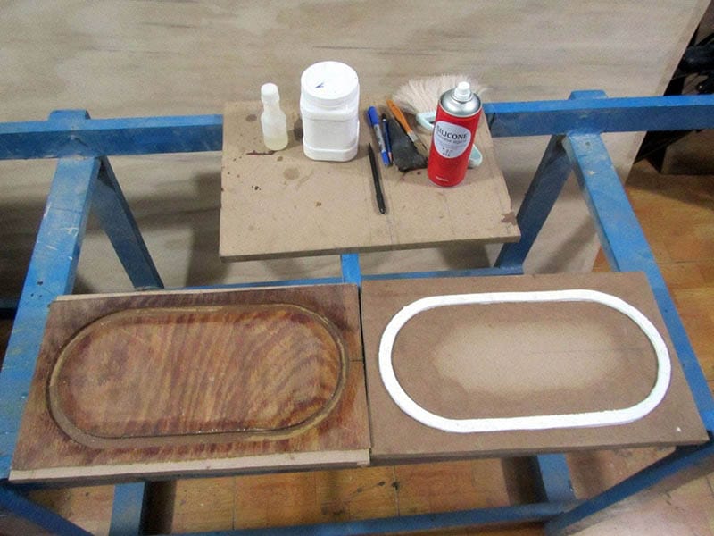
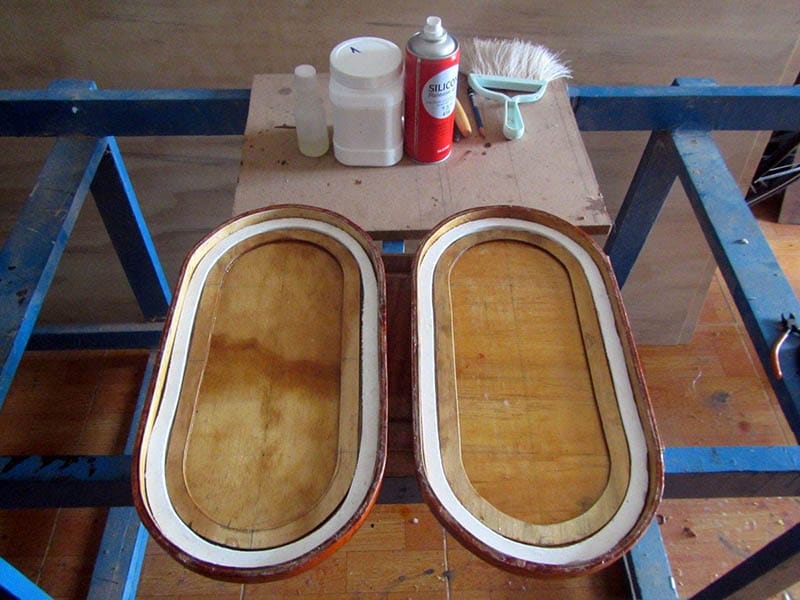
Gaskets fabrication: the critical thing in a hatch’s waterproofness is its gasket, and I realized that the best material for gasket is silicone: flexible, durable and offer a very good fit. And for a custom size and shape hatch, somehow I’ll need to make the gaskets too. It turned out to be pretty much easy, using the 2 – parts silicone available here on local market. You mix up component A to component B (catalyst, around 1 ~ 4 % by weight) and pour it into a mold, wait for about 2 hours, and it’s done.
1st image: the mold (cut from plywood) is filled with silicone, I use the “Silicone” (red bottle) spray as a mold release, it’s “strange” that silicone is used as a release agent also for silicone. 2nd image: the product, the O – ring released from the mold. 3rd image: the gaskets inside the hatch lids. The gaskets are 15 mm wide, 5 mm thick, and are pressed down to the hatch rings with those belt locks. I hope I would end up with excellent waterproofness, but let wait until “sea trial” to know better.
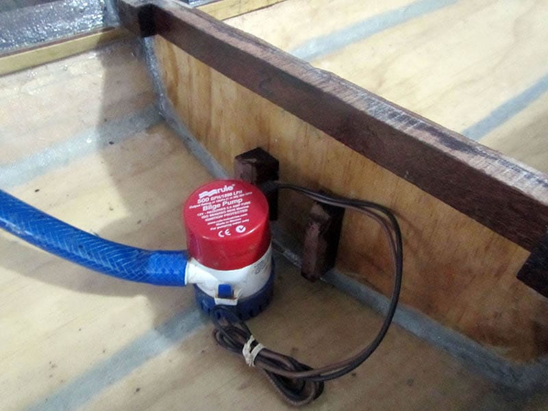
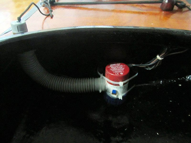
I reuse the bilge pump from my previous boat, it still sees very little use, the installation is quite straight forward using some cable ties fastening the bilge pump into its mount. The flexible water pipe leads to a hose right on the right side behind the cockpit, the hose is protected by a screw – in cap, to prevent water from leaking back into the boat when waves wash over the low aft deck. The bilge pump really offers lots of convenience and confidence when you are out there, in the roughness.
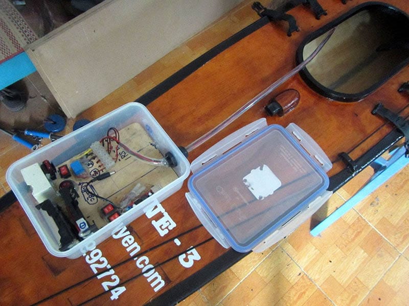
Almost ready for the water, but the tide is unfavorable for the weekend (its heights are at night), and the Tembin cyclone is crossing the East sea, threatening the area. So I take the time to complete a couple more things. Attaching the electric box through cable gland is quite straight forward, everything works out right, in essence the bilge pump and reed switch. I added one master switch to the electric circuit, in order to turn everything off and not to drain the 18650 batteries to exhaustion.
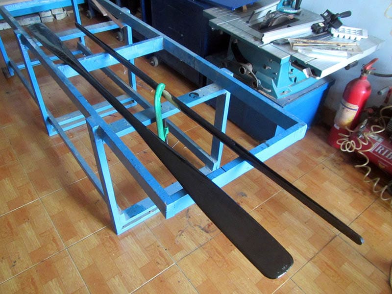
One critically important issue with the 18650 batteries is that, never used them to exhaustion, when the voltage drops below 1 ~ 1.5 V or so, the battery just becomes dead, you simple could just throw them away, a costly lesson the last time I hadn’t paddled for some weeks, and let the batteries run until dead. Next, I “refurbish” one of my old paddles to match the new boat style, turning it to black, and make it a bit stronger (and slightly heavier) with an extra layer of fiberglass.
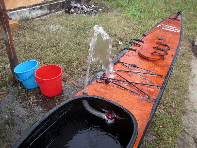
The paddle was specially built from rattan and balsa wood, and is light enough already at 0.8 kg. I would try to use this paddle first, before deciding if it’s necessary to make an extra new one, weight and durability are two major concerns. Third image: a “smoke test” to verify if the bilge pump and the solar panel all properly works. Now wait out for a few more days before going to water, just some 10 ~ 12 km of paddling, to see how the kayak behaves, how everything would feel out ther.
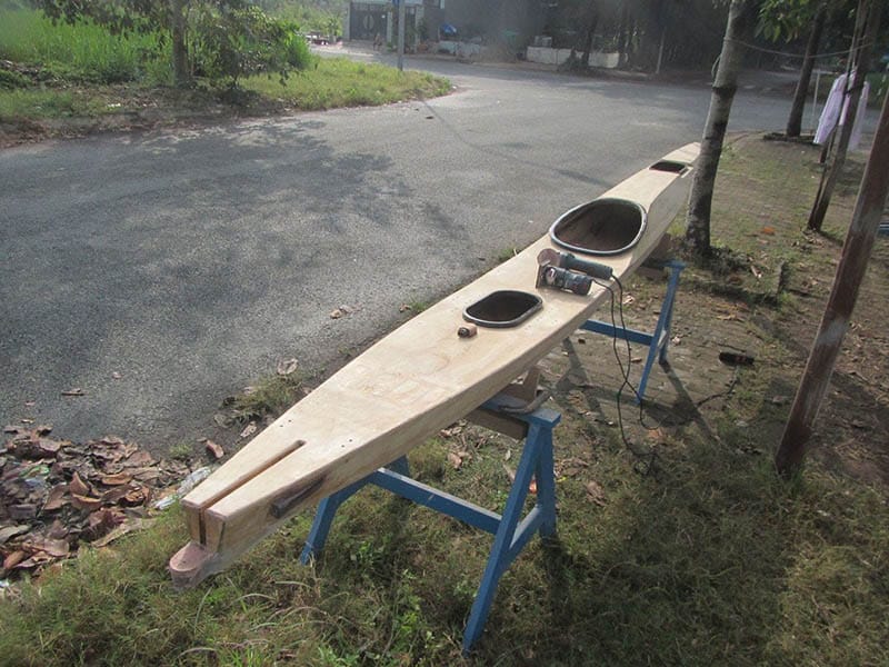
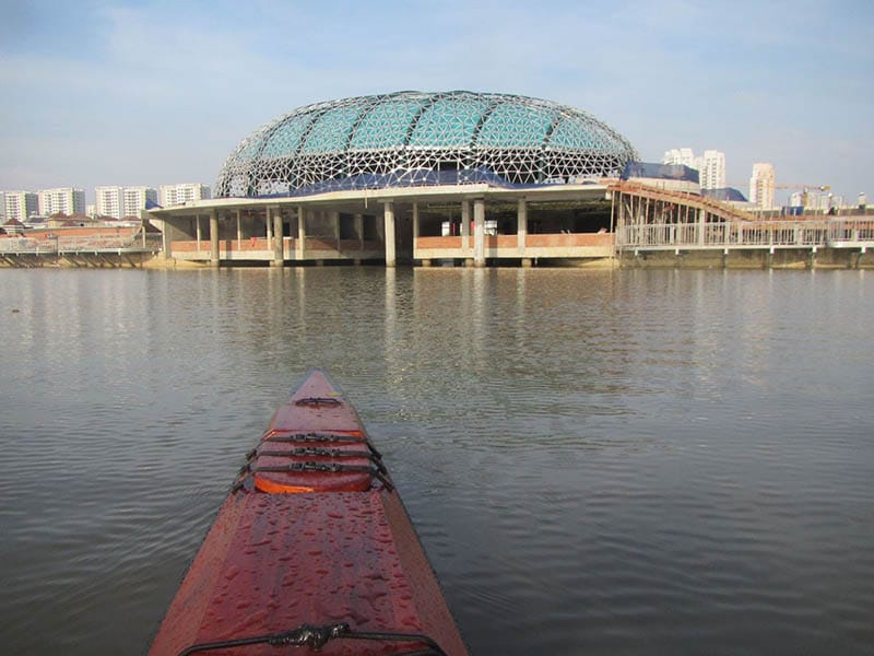
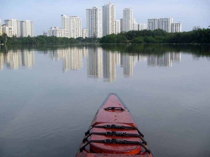
Launch the boat today, first day of the year 2018! Took the kayak out to water on a sunny, breezy afternoon for a 12 km paddling, the temperature was around 25 ~ 27 Celsius, considered “cool” with this hot – all – around – the – year tropical climate. The short paddling is just to get some first impressions, to check if everything works, and how it feels, the new hull shape, something radically different from my previous boats. Yet all confirms things I’d known from the design phase.
The kayak is nimble and very predictable, probably not too agile compared to Serene – 1 and Serene – 2, it’s also a bit more stable across all its axis. It’s easier to get in and out of the cockpit with these stabilities. The rudder works nicely, changing course instantly with just some slight pedal kicks, though I’ve come up with some new ideas to improve the “fine – tuning mechanism” for the rudder control lines’ tension (the cleats used are fine, but not too convenient for adjusting the tension).
The rudder pedals offer very good seating position, together with the plastic seat (used for testing), fixing my lower body well to the hull. I would decide later whether to just use this plastic seat, or build another lower one to facilitate reentry actions. The hatches are absolutely water tight, an important criterion! The overall feeling is very satisfactory, yet more trials are needed, in different conditions, especially on rougher water, to really understand the capabilities of this new boat.
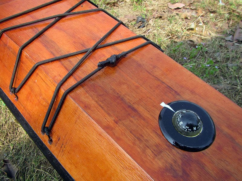
Between the trials, I managed to complete a couple of things. First is to mount the compass, the tried – and – true type of compass used in all boats of the Serene series, this without an internal lighting. Then, I built another paddle, a simple one with rattan shaft, and plywood blades, a little bit bigger, weights at 1.1 kg, slightly heavier than the Greenland companion – my “storm paddle”, 0.9 kg. Still considered an Euro – type paddle, but with a smaller blade to resemble Greenland style.
As I sometimes need larger power faces to propel the boat under unfavorable conditions. The rudder control lines are modified to be more easily adjustable, see the second image below. The pedals are attached to small segment of chains, to adjust the tension, you simple move the shackle to another chains’ eye, this could be quickly done while you’re in the field. I also replaced the bungee cords holding the pedals back by 2 large steel springs, providing better “suspension”.
Just release one pedal and the springs would pull the rudder blade back to its neutral position. I added 4 tiny 3.7V LED bulbs (series wiring) to the electric box, in an attempt to indicate the batteries’ remaining capacity (as there’s no easy way to do so). This is a trick I learnt from experiences, when 1 or 2 of the LED bulbs won’t turn on, or their brightness is drastically reduced, you’d need to plug in the solar panel then! Not all works has been completed, but it’s time to clean up the workshop a bit!
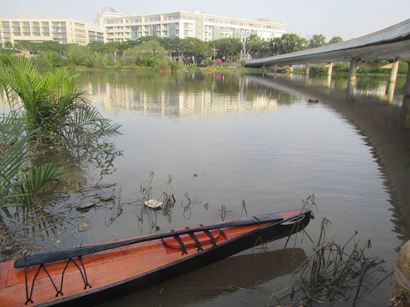
I took the kayak out for several more paddling around my area, 12 ~ 24 km, and also took a few video shots, mostly from second – person positions. I want to observe the whole boat under action, its motions and its wakes, etc… I also want to see how the rudder works, to check if the hull need some trimming, as well as to observe my own paddling movements. Actually, I’m very lazy for video capturing (and editing), they’re time consuming jobs, I’d better concentrate just on paddling.
I made a new seat from plywood, of a very simple design, composed of 3 pieces of ply bended into curved forms around a frame made from MDF. This batch of plywood is really good, no cracks, no breakages even though tortured to extreme shapes. The seat is bolted onto two “hip braces”, connecting the cockpit coaming and the floor, providing a comfortable seat, and together with the rudder pedals, offer a very tight fit for my lower body, required to control the boat in turbulences.
The overall evaluation for Serene – 3 is very satisfying, the boat behaves very well, and very predictable under different conditions. Its stabilities enable me to lean the boat to extreme angles without falling, and I really enjoy its agility, which reacts instantly to my different paddle strokes. The hatches are completely waterproof, the rudder has (more than) enough steering power, and the electric – bilge pump system works just fine. More trialling ahead on this Lunar new year holiday.
First half of 2018 is kind of a huge mess for me, everything unsettled for quite a long period of time, and I could hardly find any times to go paddling at all. You could guess what the feelings were like, when the newly – built kayak has to stay dried for an extended period of time, and the paddler dwell into a rather prolonged fatigue mood. However, things got better gradually, most of my works has come back on the right track, and it is just so wonderful to get back onto water again!
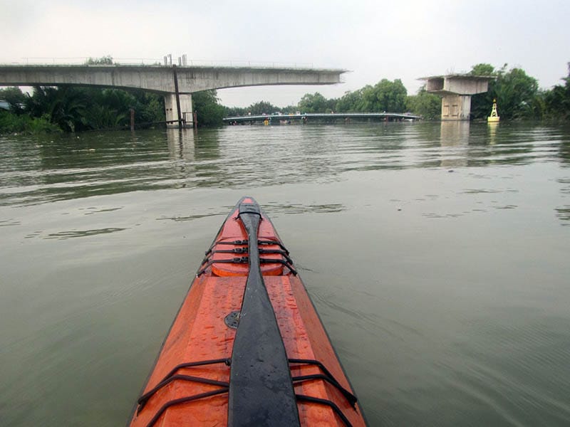
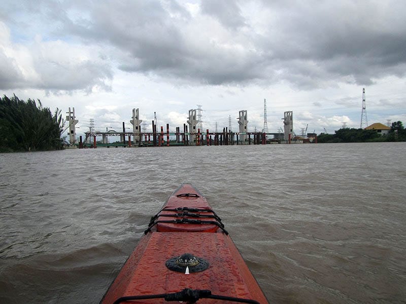
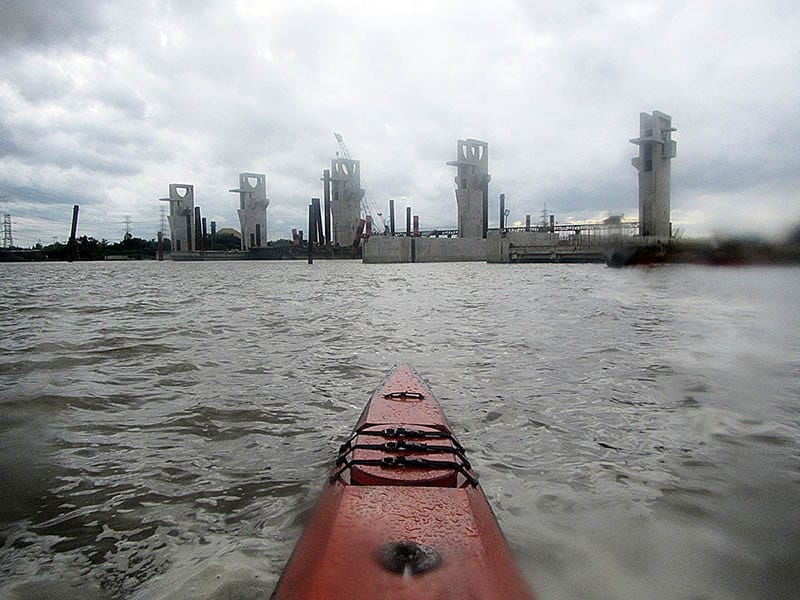
There are so many things to be tried with the new kayak! But first, just some paddling around to wake up my muscles again after quite a long period of “hibernation”. And there are so many things that happens during my idle times, the 2 large bridges of Bình Khánh and Phước Khánh are being completed, crossing over the 2 waterways (Lòng Tàu and Soài Rạp) through which the Sài Gòn river flows to the sea. But what I worry most is the 3 large dams are being built, isolating a very large area.
All Nhà Bè and 7th districts would be isolated once the 3 dams are completed, no more rising and lowering tides, just but dead – flat water, that would be a very bad news, at least for a kayak – paddler like me, as boats crossing through the dams would only be allowed at certain times throughout a day. Yes, I certainly wouldn’t want to paddle in a large calm pool of static water, that’s no fun at all. But there’s still time (1 ~ 2 years) until all these big building projects got finished and put into uses.
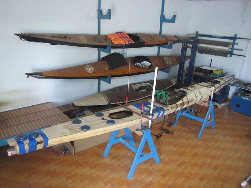
Having accumulated hundreds of kilometers with this Serene – 3, mostly paddling the water around my home area, I feel very pleased with my latest kayak! It behaves better than any of my previous boats: tracking straight, nimble and agile, while maintaining a larger stability margin. However, the last 2 years in my life have seen many big changes, ups and downs, and also, I have moved my workshop to a new place, so I couldn’t have much time for kayaking and building new equipments.
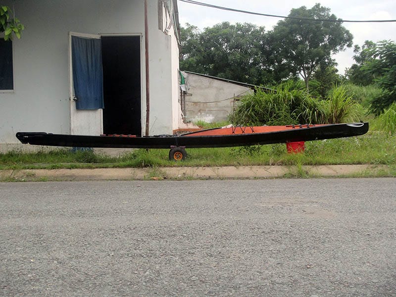
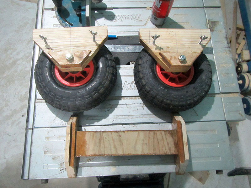
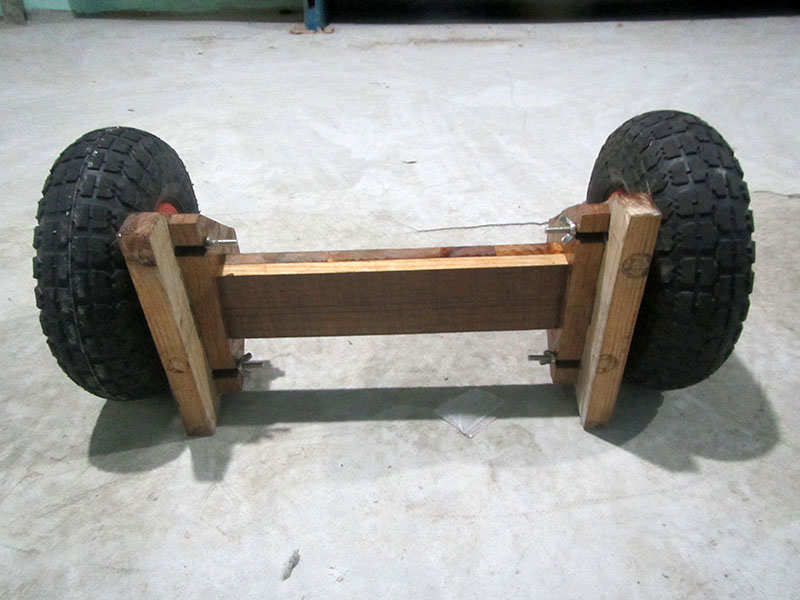
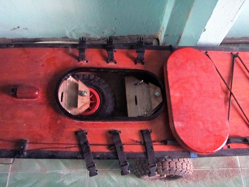
Things gradually get better, my personal life and work settled again, and naturally, I’ve got more time for kayaking. First is finishing this very – long building process (almost 2 years by now). I’ve added some few more assets to Serene – 3. A new cart is built in 3 pieces, that could be assembled / disassembled quickly. I’ve used a same – sized, but lighter pair of wheels. The cart, when disassembled, could be stored inside the rear hatch so that it won’t interfere with boat motions in action.
I’ve also built a new seat from tortured plywood, a much more comfortable one, slightly wider, with a slanted back (easier to get in / out), and a soft, closed – cell – foam back rest. The job looks easy, but really, it requires practical experiences to build a comfortable seat, the one you would probably spend many continuous hours of hard – paddling on. 4th image: the near – completed seat (without the foam block), would post more photos of the completed, painted cart and seat later on soon!
Various small updates for this Serene – 3 kayak still, I’ve could always found out somethings that could be improved. First, I’ve built a new paddle, a simple one with rattan shaft (sandwiched between 2 thin strips of wood) and slightly larger plywood blades. With lessons learnt from building previous paddles, this one is much stronger, and weights reasonably at exactly 1kg. I’ve also put some 3M reflective tapes on the paddles’ blades, which offer excellent reflection (see 2nd image below).
The electric system is redone, a new solar charge controller, better wirings for easier future changes and upgrades. The controller has 2 USB outputs (5V, 2Amp), which could charge most electronic devices. It also has better protection for the delicate 18650 battery, 6 cells in 2 blocks that totals 20 AmpH of juice! However, I still need to carefully observe the reliability and durability of the whole system, especially in this tropical climate, where temperature is of the upper 30s (Celsius) most of the time.
Once the electric system is tested and proved to be reliable, lots of things could be done based on it! First, I could modify my Garmin device to run directly on the 5V USB output, thus don’t have to use the rechargeable AA batteries anymore, power would be available “all the time”. Second, a LED torch could be also added, which directly use the 12V output from the 3 serially – wired 18650 cells. Lots of things to be experimented until the whole electric – electronics system could be finalized!
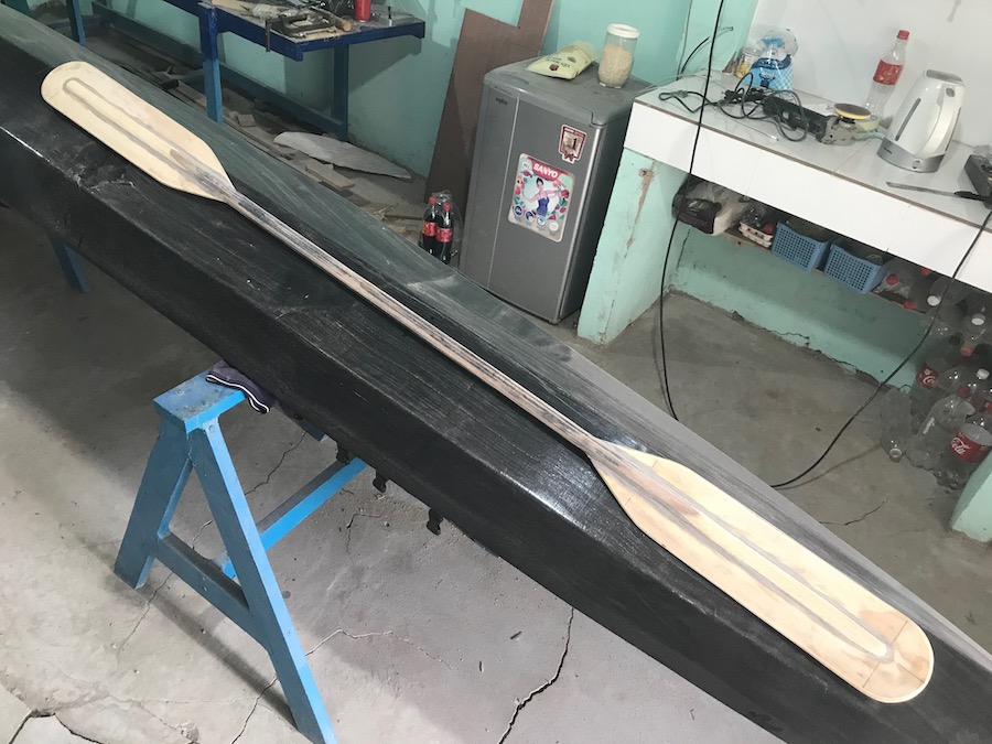
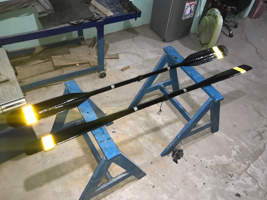
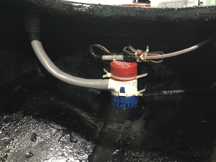
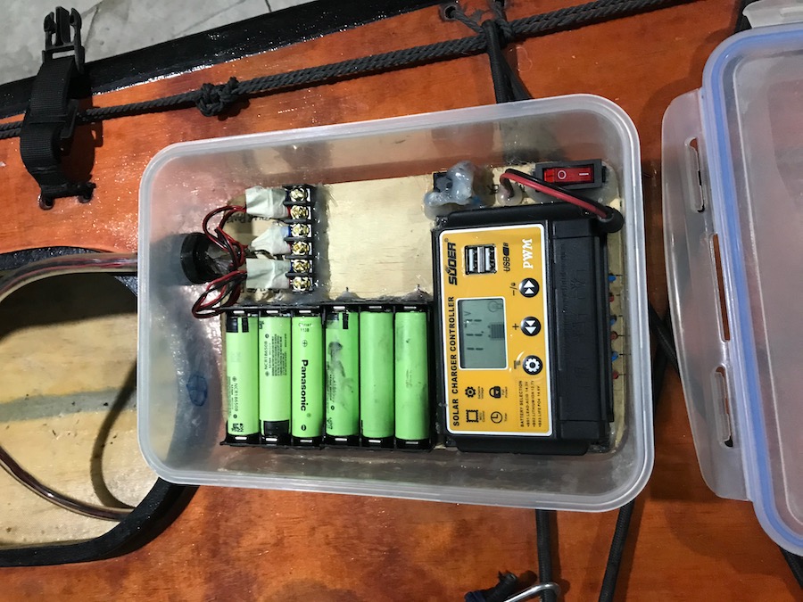
PHOTO ALBUMS
For more details, see the photo albums below:

