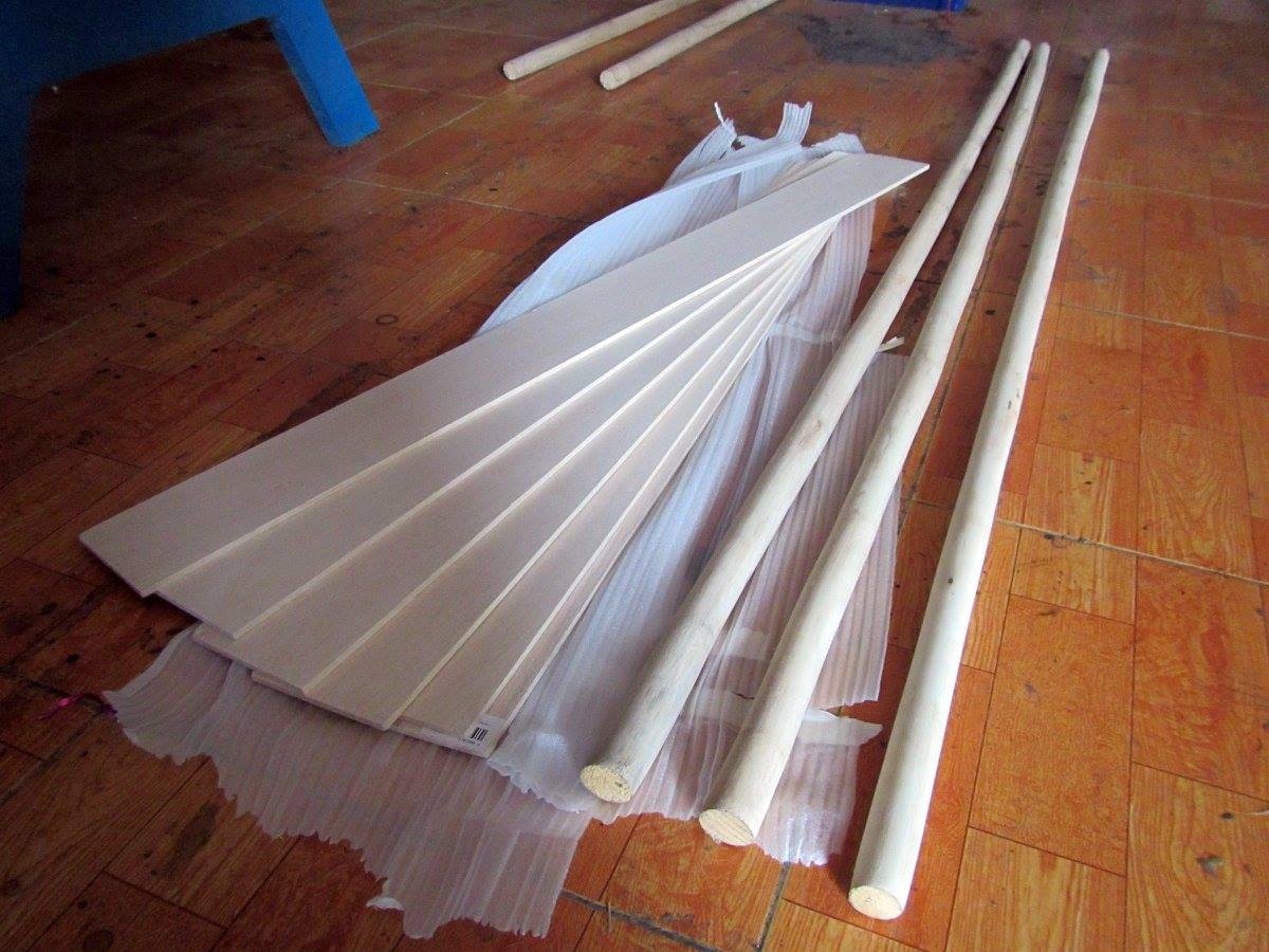
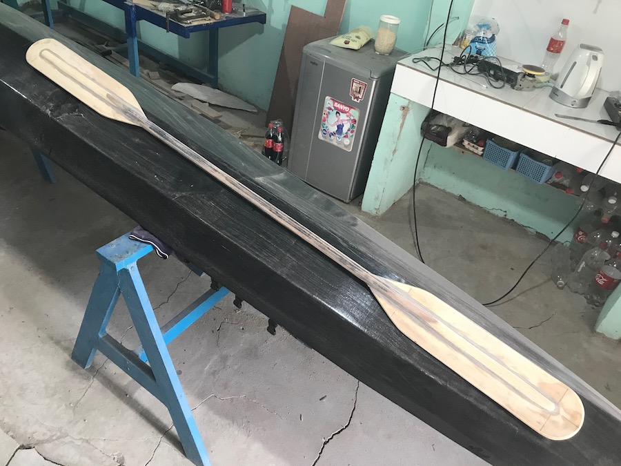
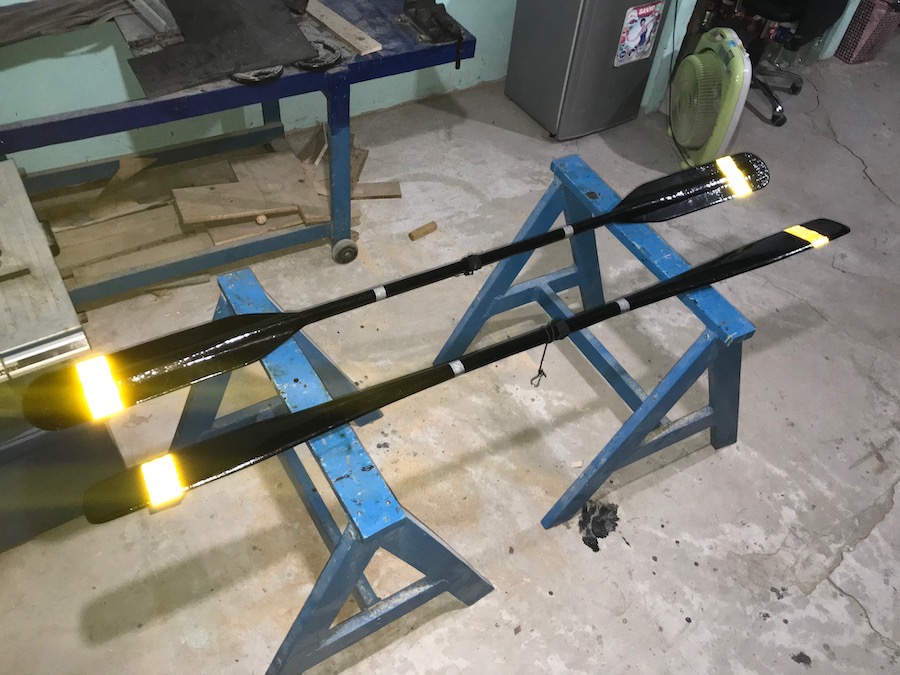
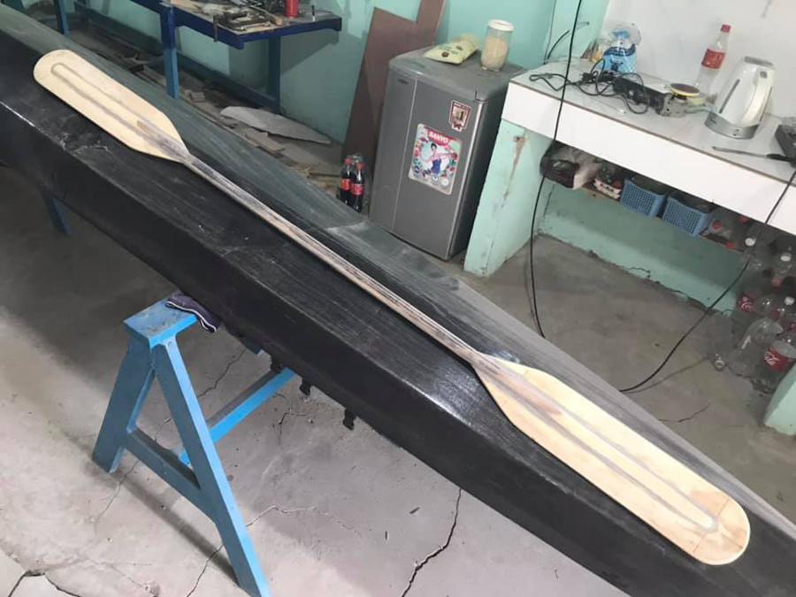
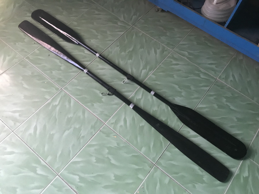
serene – 2, part 30

It’s time to join the hull and deck, and now the boat takes its final shape! The gunwales are bevelled differently along their length to better accommodate the deck, paste some putty on the bevelled edges, then I press the hull and deck together, like the two halves of a peanut shell. Everything goes on quite smoothly, the bow and aft parts fit very well, just use some duct tapes to press them together.

In the middle part, there are some small gaps (about 3, 4 millimeters), so I need to fasten them with some cables. The bulkheads fit really well, firmly holding the deck and hull. To maximize the boat waterproof capability, I carefully fill the internal seams with some more putty at places which are still accessible by my arms. The whole thing is left overnight for the putty to set, permanently forming the boat shape!

The next morning, I carefully trim the deck part. Since the deck is cut oversized, it’s slightly larger than the hull, it need to be trimmed down to match the hull, apply some more putty here and there to fill some remaining gaps, then round the seams (the external sides) in preparation for glassing the hull. Months of preparation, consideration and hard works has finally “culminated” into a seeable, touchable object!

It seems that, at this point, the boat would be able to see water in no time. But actually, there’re lots of works ahead: glassing the hull, install the rudder, rudder control lines and pedals, fitting the bilge pump and signal light, sticking the vinyl decorations (text and boat eyes), fitting the compass and all those bungee cords, various other accessories, etc… and finally varnishing the whole thing with transparent PU paint.

serene – 2, part 29

Finished all electrical wiring and device testing. It looks simple, but actually, for me, there were lots of works. First is to figure out how the relay pins work. First image: I noted down the wiring diagram of a relay, the 2 pins on the right, one is NO (normally opened) and one is NC (normally closed). The middle pin on the left (the common pin) supplies power to the targeted devices (here is the compass light, just for testing).

The two other pins supply power to the relay itself, when powered on (decided by the reed switch), the relay switches from NC to NO position, hence supplying power to the compass light. All wirings runs back to a central point: the plastic waterproof wiring box, which houses the battery, the solar charge controller, the relay… It took me some times to install all in the box, connect the correct wires, check if everything works!

The PowerFilm solar panel shipped with a long water proof detachable cable, so I run the cable from the central compartment to further aft where the solar panel would be located. This cable runs through a cable gland to exit the deck, ended with a waterproof connecter. It’s not very nice to always have this connector on deck, but it’s convenient to disconnect the solar panel and stored away when it’s not in need.

There would be another waterproof box (connected to this wiring box which would be rarely opened) which houses the 12V – to – USB and the 12V – to – AA charger, which could be usually opened to put your various devices in for charging (iPhone, VHF radio…) But that would be in another later phase of the project. It now time to joint the hull and deck parts together to form the final boat shape!

serene – 2, part 28

Next is running the electric wires. I want them to be completely waterproof, so every wire running is placed inside plastic tubes for additional protection. First image: I solder 3 reed switches with wires, place them inside the small wooden bar, seal it completely with epoxy, and glue them under deck inside the cockpit. The letters C, P, L mark the positions of the switches for: compass, pump and light.

All wiring runs back to the day hatch, where a central box housing the main battery. I just use a LOCK & LOCK plastic box, it’s pretty much very watertight, if you close it properly. All wiring tubes would be connected to the box through cable glands with silicone glue. Another issue solved is the relay, it took me an hour to figure out how the PCB relay wiring works! Luckily, I haven’t forgotten all electric knowledges learnt in college!

Since the reed switch is so tiny, it usually can’t stand the amplitude of the current required by the bilge pump. So the reed switch is used to activate another switch (the relay), which can handle the current (it’s so good a feeling to hear a small ‘click, click’ sound when the relay is activated / deactivated) The electrical, electronic parts of the project is not as hard as I’ve expected, all is done quite neatly!

Today, most equipments I ordered from Amazon has arrived: the PowerFilm 7W rollable solar panel, the SunGuard 4.5 Amp solar charge controller, the Rule 500 GPH (gallon per hour) bilge pump, a marine signal light, one Stohlquist “high – back” PFD… and some other things. I was feeling very good, as this phase of the project could be completed soon, and the boat is already somewhat quite near its completion!

serene – 2, part 27

Now working on the electrical parts of the project. From other renowned sea kayakers, I’ve long learnt about their electrical and electronic system. And my own experiences pointed out that, the need for a battery system to run a bilge pump (and to power various other devices) is very urgent and obvious. From the very early phases of this project, I’ve been thinking over and over again about it.

The system would have a solar panel, to charge into a SLD (sealed lead acid) battery. The battery is used to power the bilge pump, its primary purpose. But since now I have a 12V DC electric system onboard, I could use it to: illuminate the boat’s compass, power the signal light, and to charge various electronic devices: the iPhone, the VHF radio, the Garmin, cameras, etc… Basically, I want an independent system that power all.

First is the compass light, some white LED sources to illuminate the compass in case of paddling at night. I could just buy a compass with built – in lighting, but those such compasses are not readily available in the local market, and usually they’re a bit oversized for a tiny boat like Serene – 2. So I decided to modify my current compass to accommodate 4 white LED bulbs, the result is beautiful (1st & 2nd image)!

The most special thing in my electrical system is… the reed switch, a sealed electric switch which could be activated by a small piece of magnet (3rd image). That way, the switches could be hide and sealed inside the hull, completely covered in epoxy to protect them from water, and they could be turned on / off by the presence of some small pieces of magnet outside of the hull. I’ve found the idea… simply brilliant!

serene – 2, part 26

The deck is stained in a light – yellow color, compared to my previous boats, this kayak would receive a much lighter color scheme. Light, bright color would reveal more the defects on plywood and my building mistakes, but I don’t really care about that anymore, as soon as the faults are not too obvious. Then a thin layer of glass throughout the deck (first image). Next comes various deck fittings.

First are the cleats used to tie down the hatches’ lids. These wooden cleats are glued on, then bolted down with 2 small bolts for each cleats. I carefully fill the bolts’ holes with epoxy, then paint the internal side with some epoxy to prevent water leaking in. Tying down the hatches’ lids with lines is not a very handy way, but it’s simple and very secured, compared to other complex locking mechanisms.

Last image: the rudder control lines’ tubes exit the deck near the stern, secured by 2 small wooden blocks, and protected by 2 cable glands to make the deck completely watertight. On the other ends of the tubes are similar cable glands inside the cockpit. I also made 2 “double – ended” wooden cleats to micro – adjust the rudder control lines’ tension. Various other wooden parts are also fitted on the deck.

The progress slows down as I approach one of the last major phase of the project: electricity. This is a complex issue, the kayak would have a 7W solar panel, which charges into a 2.2 Amph SLD (Sealed Lead Acid) battery. The battery is used primarily is for powering the boat’s bilge pump, and secondarily, to charge various electronics devices: the iPhone, Garmin, VHF radio GoPro, camera, the compass’ and signal lights, etc…

serene – 2, part 25

First image: the 6 – mm diameter plastic cable glands, with a cigarette lighter for size compare. These cable glands are used at various places on my Serene – 2 kayak, but primarily used for running tubes, cables through hull. With proper installation, they should be waterproof, with the extra help of some silicone glue. Second image: the rudder control lines’ tubes, running through 4 cable glands each all the way from the cockpit.

All electric cables on my boat would be placed inside plastic tubes, to maximize their waterproof capability. So they would also need some cable glands to run through the bulkheads. But that would be the next step of the project. Now, just all things rudder related! Third image: the rudder pedals, simple pieces of wood that could be rotated around hinges. Since all these parts are quite near the compass…

So the hinges, the screws… are all made of brass. I had a hard time finding these brass parts, cause most available on the local market is actually made of steel, just copper plated. It’s quite weird carrying a piece of magnet around the shops, to verify that they’re actually non – ferromagnetic, but I have to really make sure about that! For the compass, I would just used the same type as in my previous boat.

Though a simple and cheap compass, it has been verified (in my last 9 days trip) to work correctly and reliably. Before installing other parts, I slightly sanded the deck, applied some colored – thinned epoxy (for color staining, this time, the deck also has a yellow color like my previous boats, but much a lighter shade). Next would be glassing the external side of the deck, before fitting many other parts onto it.

serene – 2, part 24

There’re quite a lot of works required on the deck. First, I need to make various small wooden parts: the bungee cords’ anchor points (14 of them), the cleats (6) used to tie the hatches down, the rudder post, wooden balls for line pulling, etc… all is very “small” wood working, you would need to work on parts that a just a few centimeters in size, an ugly type of work which I don’t like, since I don’t really have skillful hands for that.

Second image: various wooden parts. First image: cut half – curve grooves for making the bungee lines’ anchor point using my router. The bungee would loop through that grooves, going from the external side, through the deck, then back to the external side again. There’re 14 anchor points like that to be installed, 8 around the cockpit, 4 on the aft deck, and 2 on the fore deck. Here, I learn to cut with the router following a template.

Third image: fitting the cockpit anchor points, the installation is quite simple and straightforward, the wooden blocks are glued on, with steel wire fastening through the holes, later some little putty would be filled in the jointing edges, and maybe some glassing too. This way, the bungee cords’ anchor points are made so simple, easier to implement, not the same nasty, clumsy way as in all of my previous boats.

Next in installing the rudder control lines’ tubes. Those are 6 – mm diameter (4 – mm internally) plastic tubes that run from the cockpit, through the day – compartment and aft compartment to near the stern, running through 4 cable glands on the way for each tube. The installation is quite messy, as I was using too much silicone glue, in an anxiety to assure that these cable glands would be completely waterproof.

serene – 2, part 23

Installing the cockpit coaming and hatches is quite straightforward: the fore and aft hatches, and the day hatch. Then I bevel the deck’s jointing seams (the external side) a bit, as well as the cockpit coaming, the seams need to be curved in order for glassing to go on well. Glassing the cockpit coaming could be a little bit tricky, as the fiber fabric should wrap around and cover both the internal and external sides.

Talking a little bit more about jointing the seams here. For the seams to be strong, I follow these 3 steps: first is priming the seams with some epoxy, then when the epoxy has not cured, apply the putty. Putty has lots of viscosity, so it won’t penetrate well into the plywood, that’s why we need epoxy as primer. And once the putty has only half – cured, I apply the glass tape. That way, the seams would be very strong.

First image: fitting the hatches. The hatches’ bases would, from beneath the deck, go through the cut – out holes, they serve as reinforcement rings around. Since the hatches’ bases and lids are of the same height, going through the deck would leave a small gap (about 4 mm) between them. That would be the place to pour some epoxy in, the type of elastic, softer epoxy which functions like the hatches’ gaskets.

I didn’t glass the internal side of the deck, just some fiberglass tapes at the seams. Instead, the deck would be glassed on the outside, which should offer better protection against water. The internal side only receives a very thin layer of epoxy coating. The external glassing would slightly overlap with the hull (about an inch), to better strengthen the deck & hull joint. It looks like basic jobs are done? Actually there’re still lots of works ahead!

serene – 2, part 22

Continue working on the new deck! The deck has 3 bulkheads of its own, corresponding to those of the hull. The two rudder control lines would run inside plastic tubes, which run through these bulkheads via waterproof cable glands. But that would be later, first is installing the cockpit coaming, which is just a thin plywood strip bending around a MDF frame. The coaming lip is also cut from plywood.

First image: you can see my beloved Fein Multi Master, the renown oscillating tool. Often when I have to cut or do other tasks in tight corners or in positions that are inaccessible or inconvenient to other reciprocal tools, this Fein is my last resort, and it’s always been very helpful to me. Here, I need to trim the already installed, but wrongly – sized bulkheads. Also, really love the tool’s Germany quality.

There’re some other tasks which are not reflected in the images here: fairing the hull and deck’s external seams, then glassing them with my fiber tapes. It’s not until now that I could comprehensively master the skills working with epoxy and glassing, using just the right amount of them. But also, I also gave up the idea of a kayak that’s as light as possible. For a training, exercising boat, lighter is of course better.

E.g: 15 vs 20 kg is a huge different, cause it’s much easier to launch and retrieve the (almost empty) boat for every training sessions. But for an expedition boats, a few kilograms doesn’t make much difference, since a loaded kayak weighs as much as 110 ~ 120 kg, with that mass, you can’t carry on your back anyhow, so a few more kilograms added would worth the value of a stiffer, more durable boat prepared for long journeys!

serene – 2, part 21

A major setback in the building progress, the curved deck didn’t come out with my expected quality. After released from the molding frame, the deck slowly bend back from its curved shape, especially amid of the boat, off from the desired geometry by 3, 4 cm (first image). That’s really bad… I made a hard decision to discard the rounded deck, and build a hard – chined one (like my previous kayak) instead!

I had an uneasy feeling, lots of work has to be redone, cutting and jointing the deck’s bilges (second image), setup the molding female frame. I took this chance to modify the deck design a bit, raising the aft part by 1 cm, to better accommodate the rudder control lines. A hard – chined deck doesn’t look as good as a rounded one, but it’s easier to build, easier to install other things, and it would fit with the hull much better.

Third image: forming the deck shape, the geometry is so simple that it doesn’t need any wire – fastening, just some CA glue here and there to fit the bilges together, some duct tape on the outside, then putty onto the inner seams. To save weight, I only glass the deck internal side at the cockpit area, where it could be potentially exposed to water. However, the deck would receive a glassing on the external side later on.

Fourth image: dry fitting the deck and hull… perfect fit! No adjusting, no fastening, no compressing would be required, just fit them together, then trim the edges! In the image, top of the cockpit area, we can see the cockpit coaming template (cut from MDF). That would be a frame for building the coaming lip and ring around, measured 38 x 64 cm in internal dimension. The external dimension would be 44 x 70 cm.

serene – 2, part 20

With my Dremel – Multi – 3000 tool, I made lots of parallel cuts onto the deck internal side (see the first image), the cuts are about 1.5 cm apart, and about 1 ~ 1.5 mm deep. Those are not very deep cut, since the plywood is only 4 mm (3.75 mm to be exact). Then I soak the deck with water thoroughly, for the ply to be softened, then put it into the frame and press it down… with my body weight (just sit on it).

With the extra help of some clamps, I press it down, little by little, don’t be too quick, just do it very slowly, then the plywood bends nicely into a perfect curved shape! There’s some minor cracks on the edges, but that’s not too important, cause those parts would be trimmed away when the deck would be glued with the hull. Second and third images: you could see how well done the curved deck is!

I let it there overnight, waiting for the water to vaporize, then apply some thinned epoxy onto the deck internal side, I also apply a few glass tapes at some places, that way the curved deck would hold its shape once released from the molding frame. Next would be puttying the rear part of the deck onto the forward part, a simple and straightforward job, then again, glassing the seams with my beloved fiberglass tapes.

Joining the fore and aft parts of the deck is quite simple, though it required some wire fastening to put everything under order. FreeShip (the boat design software) strangely generates a slightly abnormal curve around the cockpit (had I made some mistake, or didn’t use the software in a correct way?). So I had to manually draw the line by hand, guessing at some places, resulting in not a very good fit.

serene – 2, part 19

First image: the basically completed hull, put aside, now working on the deck part. Compared to the hull, which is… simpler and more well defined in term of geometrical shape, the deck is just loosely draft out in overall shape, it’s cut slightly over size, so that when fitted together with the hull, it would be trimmed to match. The construction is also more complex, due to the rounded shape of the forward part.

I had a hard time thinking about the cockpit and spray skirt size. A width of 44 cm is almost the minimum that could fit a cockpit, that in turn, could fit the smallest spray skirt sold on the market. Ready – made spray skirt (e.g: Snapdragon, Seals, Sea to Summit…) usually have 44 x 75 cm as the smallest dimension, other than that, you would need to order a custom made one, which is an expensive and complicated process.

Second image: drafting out the deck shapes on plywood. Third image: jointing the pieces together, again with those simple finger joints. Fourth image: the two main “components” composing the deck, the aft (far, left), and the front (lower right). I slightly bevelled their edges at places, so that they could fit more precisely together. The white duct tape: pin down the parts so that they’re correctly symmetrical along the longitudinal axis.

Next is the very important job of torturing the deck into rounded shape. By now, I’ve realized that there’s too much curvature on the molding frame, and I wonder if the plywood could bend that much to make a very curved shape, only experiment would tell. In order to help the ply bending well, I would make many longitudinal cuts on its internal side, then wet it completely overnight for the wood to become more flexible.

serene – 2, part 18

After the internal side get glassed, goes in the gunwales (American English: the sheer clamp), port and starboard at the same time. The gunwales are very thin strips of wood, 2.5 x 1 cm in cross section, and are bevelled at 45 degree all along its length (they are bevelled with my table saw), later the bevel angle would be adjusted along the boat hull (with an angle grinder) to better accommodate the deck.

Second image: the 3 bulkheads, the small compartment right behind the cockpit would be the place of the day hatch, to store food, drink and other various things you would frequently need during a paddling day, and could be accessed while afloat (still sitting inside the cockpit). For other hatches, you would need to beach the boat in order to access them. Third image: the bulkheads are filled with putty at the joints and glass on one side.

Fourth image: triangle blocks of wood use to reenforce the joint between the gunwales and the bulkheads. With no need for nail or bolt, the triangle wooden blocks link the squared corners, this way, the kayak’s “frame” would be significantly stronger, stiffer, a simplest, yet elegant solution. There’re two additional thwarts installed near the bow and stern to strengthen the boat’s overall structural stiffness.

Completed most jobs with the hull (there’re some more on the external side of it – puttying, glassing… but that would be a later phase of the project), now moving on to the deck part. It doesn’t seem immediately apparent, but the deck part is a more complex part, compared to the hull, it would house many things: the 3 hatches, the compass, the rudder pedals and control lines, the anchor points for bungee cords, etc…

serene – 2, part 17

Finishing the fist step of forming the hull into shape, then filling the seams with putty and glass them with my 2 – inches fiberglass tape. The glass tape is my life saver, thanks to it helps again, that the seams could look neat and nice. To this day, I’ve acquired enough experiences and skills working with epoxy and putty already, so I’ve been able to mix the very precise (usually very small, e.g: 30 ~ 60 gr) amount required for each task.

Remember my very first days coming to boat building, working with epoxy has been a nightmare, that extremely sticky substance that messes and flows around. I have a very good feeling that everything is completely under my control in this build: the bilges fit tightly, the bulkheads fits very well, there’s no need to adjust here and there, the amount of epoxy and putty used could be estimated with quite an accuracy.

Second image: dry fitting the bulkheads, this time the cockpit would be slightly larger, to accommodate the bilge pump, and the rudder control pedals. Third image: fitting 2 prism – shape wood blocks at the two ends of the kayak, one at the bow for getting the pulling line through, and one at the stern to mount the rudder post. Again, very little epoxy and putty used, the wooden blocks add some saving to the final boat weight.

Fourth image: glassing the internal side of the hull, I’ve been thinking over and over again about this issue, do I really need to glass the hull internal side, consider the glassing seams are quite strong already. Finally, I decided to glass anyway, as my plywood is not of very good quality, it’s better to have some protection in the long run, with the cost of about 0.4 kg of epoxy (plus the fiberglass fabric) added.

serene – 2, part 16

Fitting the bilges is quite straight forward. Compared to my previous boats, this time, due to more careful drawing and cutting, having a good shape, the bilges fit together pretty much better, there’s almost no gaps between them. It requires still some little fastening with wires, but not much, and some dots of CA glue (cyanoacrylate) to help the edges staying head – on. Then I proceed to filling the seams with thickened epoxy.

First image: the bottom pair of bilges fit together. Seeing them fitting so well to the molding frame, I decided to putty – fill and glass the bottom seam before adding the second pair of bilges (second image). I really appreciate my 2 – inches – width fiberglass tapes, they help the seams to be very clean and tidy (and hence less epoxy used). With out them, fiberglass cloth bias cutting would be a nightmare for me…

…As the kind of fiberglass cloth I’m using is not too good in quality. Third and fourth images: the second pair of bilges goes in, also very good fit, requiring little fastening. Due to the sloping sides of these bilges, filling the seams with putty could be tricky, as the thickened epoxy wouldn’t hold shape but flowing down slowly due to its viscosity. So, I apply a small amount of putty, then immediately cover them with duct tape.

This way, the epoxy would hold shape, leaving a good looking seam. After the epoxy completely cures (about 8 hours in my case), I peel off the tape. It’s so good a feeling to see your boat take its initial shape. I spend sometimes standing, watching the bow and stern, its full water line, its slim and sleek lines. Still many things to be done, but this gonna be my Andalusia horse on the wide wild wet water space!

serene – 2, part 15

Proceed to cutting and jointing the bilges. This step is done quite quickly as I’ve now had plenty of experiences. I read the offset – table directly from the FreeShip software, then draw the bilges on the 122 x 244 – cm plywood sheet. For the 17 feet hull, there’re 3 pieces per bilges, and hence, 2 joints need to be made for each bilges. I clamp 2 plywood sheets together and cut the port & starboard parts at the same time.

It takes some little skills and experiences to make the joints perfectly fit with just a jig saw. And I still prefer the straight finger joints as used on my previous boat, they are simpler to cut, simpler to align and to make sure that the jointed bilges are in correct shapes. Too bad, my plywood is of too poor in quality, it’s so fragile, so easy to crack, so I have to take extra cares at this steps, or the “fingers” of the joints could break.

First image: transferring the lines from offset table to plywood boards (with the help of a cup of coffee, be careful not to make any mistake). Second image: all pieces cut, third image: the finger joints (no glueing yet). Fourth image: jointing the pieces together with epoxy (just use many weights to press on), then glassing them (the internal sides) with one layer of 6 – oz fiberglass.

Decided not to bevel the bilges’ edges, though beveling helps making tighter seams, my plywood is quite thin, so the seams wouldn’t be very perfect, they hardly could stay precisely edge on edge with each other (and beveling adds some more works to be done). With Serene – 2, I proceed with the hull first, then the deck, not doing them in parallel like my previous boat, as the deck part could be quite complex this time.

serene – 2, part 14

Framing for the deck is more complex than the hull, since the deck would be curved in cross section, it require torturing plywood to a considerable degree to acquire that shape. From my previous experiences with bending plywood panels, I decided to break the deck framing into 2 parts, one is female, the other is male in shapes, then compressing the plywood sheet in between using many G – clamps.

First and second images: cutting the deck framing stations, can see clearly that the upper and lower parts of the deck frame are cut from the shame plywood sheets. Unlike the hull’s stations, which is positioned at an interval of 60 cm apart, the deck’s stations are placed denser, one for every 30 cm. The deck plywood would be tortured between these upper and lower stations to achieve the desired curved shape.

Bending plywood, particularly the 4 – mm thich ply I’m using, could be a hard task (and currently I don’t have any 3 – mm or thinner ply readily for making the deck). More over, the plywood I purchased is not of very good quality, it could crack too easily. So I would need lots of tricks to get the job done: soaking wet the plywood overnight with water to soften it, using hot boiling water to soften it even more.

(Currently I don’t have any wood steaming device, and there’s no plan to build one just yet.) Another trick for bending plywood is making shallow cuts longitudinally onto one side of the plywood sheet for it to bend easier. Fourth image: the curved stations of the deck glued on. Now all jobs related to the framing is done, next would be proceeding to cutting and joining the bilges… the long and hard way is still ahead!

serene – 2, part 13

Simple thing that is done many times already, since the very first time I was building the Hello World -3 kayak, so there is nothing special about setting up the “female” frame for shaping up the kayak hull and deck. The stations (as called so by the software FreeShip) are placed evenly at an interval of 60 cm, there are 8 of them for the 17 feet (approximately 518 cm) hull. All is cut from 18 mm – thick MDF.

First image: the stations cut, second and third images: since the 18 mm – thick MDF I used is at the maximum that my compress – air staple gun could handle, I simple glue the stations on along a MDF board, each 60 cm apart. You can see the stations numbered, from H1 to H8 (from stern to bow). Fourth image: another view of the completed female frame, looking this way, one could see that the kayak hull is so slim. It’s so indeed!

At 44 cm, this Serene – 2 kayak is just slightly narrower compared to my previous boat. Serene – 1, which was at 45 cm. One of the main reasons why it took me so long to start this kayak building is that, I greatly appreciate my previous boat’s abilities in rough water, it did give me a lots of confidence. I wouldn’t want to lose that very special capabilities along my design progress, while improving some shortcomings…

…That my previous kayak had had. It is a very good feeling watching the “female – molding” frame, which gives me a very first impression on how my future boat would look like. But the long way is still ahead, it would take much efforts in completing my “perfect sea kayak”! By the way, the “rule” for choosing a sea kayak hull is that: build / buy a longest and thinnest one that you could still find it controllable and comfortable!

serene – 2, part 12

Not entirely related to this Serene – 2 building, but I would want re – organize my woodworking workshop a bit. My working place is quite small in floor area, so everything need to be stored neatly and tidily. Having quit some ideas, but would carry them out only one at a time, since I still have limited free time in the present. First is a shelf to store my plywood and MDF sheets (lots of them), and many other things.

The plywood and MDF sheets need special treatments, they could deform in shape or absorb moisture if stored inappropriately for a long time. The shelf would have two sides, the sloping side is for storing the sheets, and the other side is reserved for other things. The whole thing would be put on 6 small wheels so that it can be pulled and repositioned around the workshop, or moved just for cleaning the floor.

1st image: making the shelf base, 2nd image: the 3 supporting walls (to withstand the MDF and ply sheets’ weight, which could be very heavy). 3rd image: the shelf taking shape, 4th image: the completed and marine – blue painted product, ply and MDF sheets stored on one side (facing the wall). I need lots of shelf spaces to store various miscellaneous assets, which is growing to a unmanageable number.

Sometime, I’ve forgotten that I’ve purchased something just because there’s a huge pile of them around. The workshop looks very tidy now, having more spaces to store various things. It’s very important to keep thing tidy, uncluttered, as you wouldn’t want to waste time finding an item when needed. It’s now time to move on to the main parts of the project, I’ve been lingering around on other issues for long enough.

serene – 2, part 11

First image: assembling the rudder’s components, the rudder in its dropped down position, 2nd image: the rudder in its retracted position. Everything works smoothly as calculated, the blade could be pulled up and down by a pair of line running back to behind the cockpit (but that would be done later, when attaching the rudder to the kayak hull), with two circular ratchets glued on the two side of the rudder blade.

4th image: the rudder stained with colored – epoxy and then painted (with transparent PU – PolyUrethane). It looks so nice, the dark brown color with coarse wooden grains. The rudder control system is another complex problem, but that I would address it later on on the following phases of this building project, as I’m still hesitating between the two styles of rudder steering mechanisms as described below.

One style is the T – bar of those Olympic kayak, and the other is the normal 2 – pedals usually found on touring boats. The Olympic style is simpler, but it’s quite counter – intuitive as you would have to use the left leg kicking the bar to the right, in order for the boat to turn right. The 2 – pedals system is more user – friendly, you simply kick with the right leg to turn right. I also may use kind of a cross between the two mechanisms.

This is the first time I use a rudder, so many consideration and calculation have to be made. First in designing the hull, the hull should work efficiently and independently without a rudder, that is, it should track straight in most circumstances. Only under extreme turbulences that the rudder should be deployed, to save yourself from the extreme fatigue of one side paddling, or to have more responsiveness to the moving water.