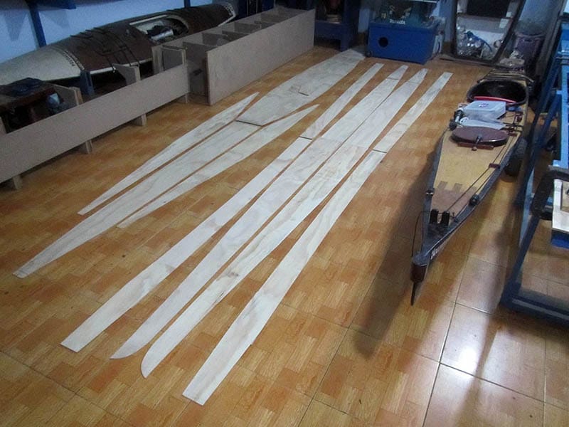
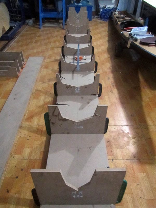
serene – 3, part 8

took great care in aligning a bilge’s parts, to make sure the final piece would come exactly to it designed shape, and to make sure the port and starboard bilges are identical, or else, the boat would have a twisted hull. All joints is slightly sanded, and applied a layer of glass on the internal side. Next come the job of putting everything together using a combination of fastening wires, super glue and duct tape. Having experiences from previous boat, I used very little steel wires this time.

It’s so good to see the bilges fit naturally into their position, with minimum pressing, adjusting efforts. The tendency to take shape easily proves that you’ve all done right in the previous steps: measuring, drawing, cutting and jointing the biges. This is for the first time, you would have an initial impression, of how the boat would finally look like. The computer 3D renderings are too small to have a precise assessment, and of course, it’s always much more lively with a tangible object! 😀

Looking at these two halves: hull and deck, having a senses of every details, it’s easier to arrange and schedule the next tasks. There’re so many jobs ahead: make and install the (recessed) hatches, hatches’ locks, install the cockpit coaming, rudder pedals and control lines, compass, the bilge pump, etc… and of course the whole complex electric & electronic system. Things should be better done this time, with the lessons learnt (tediously and expensively) from previous boat projects.

serene – 3, part 7

n parallel to cutting, jointing the bilges and forming up the hull and deck parts, I’m also making the cockpit coaming and hatches. They both use the same techniques of bending thin strips of plywood (2 layers of them) around a MDF frame to form the lips’ shape. Now that I have some much better – quality plywood sheets, which is not too easy to crack while bending into extreme curves, this enables me to construct the cockpit coaming and hatches in a much easier and convenient way.

Both 2 hatches would be of the same shape and size, a “rectangular” with 2 circular ends (or could be called: a rounded rectangular). The hatches’ lips and the coaming lips are built up from 2 layers of 4 mm plywood strips, glued together. The flexibility of the ply serves well to the building, the lips take up shape easily, and stay in that shape steadily. In all, they’re all simple really constructions. Special thing about the hatches this time is that they would have elastic silicone gaskets inside.

Recently, I’ve learnt about silicone molding, using 2 – parts silicone mixed together just like epoxy. So I would mold the gaskets specially to accommodate the hatches, and would describe that in another following post. Hatches’ waterproofness has long been a serious issue to me, hopefully, I could resolve it completely this time. An handy (last resort) trick could also be useful: cover a layer of (very thin) PE plastic over before closing the hatch, that would make it absolutely water – tight.

serene – 3, part 6

ext is jointing the plywood pieces: 8 joints for the hull, and just 1 for the deck, to form the bilges that would build up into the boat shape. For the 2 pairs of hull’s bilges, I flip one pair by 180 degree when drawing on the boards, so that to distribute the joints at different places across the boat length, and not to concentrate too much joints into one proximity. That old boatbuilding carpenter’s trick is not completely necessary with modern building techniques, but it’s nice to do so anyway.

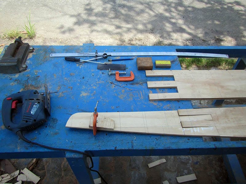
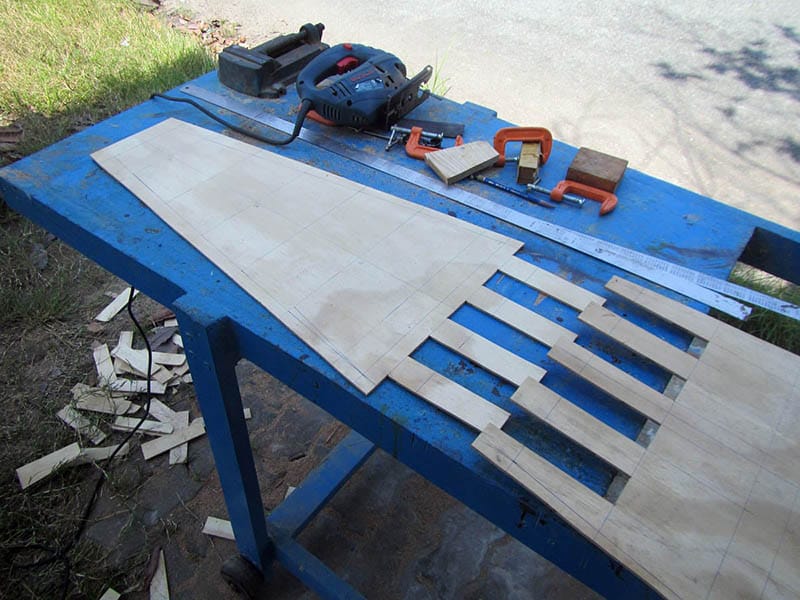
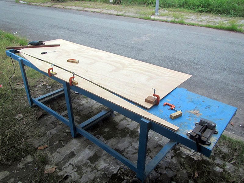
The tried – and – true technique of straight finger joint is used as always. The straight joints are easy to cut, and most importantly much easier to be aligned following a straight line for all the jointing parts, so that to make sure all the bilges would be jointed into the correct shapes. All the joints are treated carefully, first is applying a layer of thinned epoxy (using xylene as a solvent, for the substance to penetrate deeply into the plywood), then gluing with epoxy, then a layer of glass on the internal side.

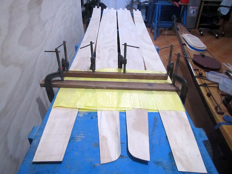
I beveled the edges of the deck parts a bit (at 45 degrees), so that they would fit tightly and nicely together forming straight seam lines. But that’s not applied to the hull, where the cursive seam lines don’t like very thin edges. Experiences from my previous boats showed that, it’s best just to use the squared edges, the thin edges doesn’t stay on each other very well, and would deform, distort the seam lines! You would later just apply thickened epoxy on both sides (in and out) of the seams!

serene – 3, part 5

he progress is really slow lately, several weeks passed, but little get done 😢! Things started moving anyhow, I “quickly” transfer the “offset tables” onto the plywood boards, draw all the bilges, bulkheads, and other parts. The greatest thing of all is that now I’ve purchased very good sheets of plywood, not truly marine – grade (there’s no such in Vietnam), but high – grade water – resistance ones. I could feel it when do the sawing, the boards are quit tough, not fragile as with my previous ply!

There would be an immediate consequence with the new plywood, I would just use less epoxy to pre – fill the boards, and since the boards is stiffer, the glassing would be done on the outside only, that would significantly save the boat weight, I hope. All drawing is completed quickly, I finished in just less than one day, next come the steps of cutting and jointing the bilges. Everything has been done many times before already, so I didn’t have to think or consider things much, just repeat it!

4th image: the cockpit coaming frame cut from a piece of 18 mm MDF. This cockpit is drawn using the mathematic formula mentioned in my last post. It came very closed to the shape of Serene – 2‘s cockpit, but slightly smaller on each sides by about 5 mm, so my existing spray skirt should fit tightly with this new coaming (on Serene – 2, it’s too tight). The coaming would be constructed from 2 layers of 4 mm plywood, and I would later omit out the (a bit tricky) glass reinforcement on this part!

how to draw a kayak cockpit mathematically?

ver the years of designing and building wooden kayak, often a recurring question comes to my mind: how can we precisely construct a kayak cockpit shape in a mathematical way. Today, I spent 30 minutes to figure out the problem, it turned out to be quite easy indeed. But first of all, there are so many different shapes for cockpits, and everyone may have his / her own preference on how it should look like. Here I try to plot a shape that is most suited to my eyes, and closed to what’s usually called “an ocean cockpit” found on Greenland kayaks.

I went to the Wolfram Alpha website (wolframalpha.com) and entered an ellipse function. Apparently a cockpit shape is not elliptic, but rather an asymmetric “egg shape”. I tweaked around the equation for a while, changing its components, and the shape came out, closely resembles that of my Serene – 2. I’d also tried to construct other types of “egg shapes”, for example, an 3 – ellipse that has 3 foci, something that could be drawn with closed thread of rope running around 3 nails pinned on a wooden board (similar to drawing an 2 – ellipse with 2 foci).

But it’s hard to determine the dimensions of that 3 – ellipse, and the positions of its 3 foci. Finally, I found out the formula that is best suited for me, something that could be determined numerically to ease out the actual drawing. The formula finally: x2 + 3.5y2 + 1.5xy2 = 1. Upon close inspection, the “egg shape” turned out to be very satisfactory. One might try changing just the “weight” parameters (e.g: 3.5, 1.5…) and retaining degrees of the polynomial’s terms, to experiment with different other shapes, to figure out what is best according to one’s need.

Next come the question of how to draw this shape onto the wooden board that would actually construct the cockpit coaming? A bit of thinking has the problem solved too. The Wolfram Alpha website provides us with numerical formulas. The general steps are like this:

1. Draw a bounding box in the dimensions you want, mine is: 39×72 (cm), the dimension that your spray skirt would fit into (and the spray skirt vendor usually supply you with this information before – hand). The x value would have the value range of [-1, 1].

2. Draw a dense grid of x & y inside that bounding box, for each value of x from -1 to 1, calculate the y value with the formulas given above. Giving very fine incremental values of x, say every 1 or 2 cm, it would be possible to construct a good looking “egg shape” then.

Of course, I want to find out a way to draw the “egg shape” more precisely and more conveniently, e.g: print the plotting actual size on paper, but found it a bit cumbersome as I have no printer of that size! Anyone finding out a good way, please kindly let me know! 😀

serene – 3, part 4

inally, I managed to have some time slots to start the kayak building. Works would be carried out mostly at weekends, and hopefully, the boat could be finished within this year. After much hesitations, procrastinations, and considerations into the very details, I’ve incorporated quite some “innovations” into the final design, as well as some “simplifications” to ease the building process. I “hope” this is also my “last” stitch – and – glue boat, the 6th of “the fleet”, seems to be a lot already! 😀

The past 2, 3 weeks were spent mostly on reviewing, fine – tuning the design, “rehearse” the overall building techniques and process. This is a design that consumes my brainstorm the most! Many building steps could be done very quick now, as they have been done 5, 6 times already. So I would skip documenting in various parts, as they are all similar as in my previous boats, only to highlight things that are different. First is setting up the molding stations, cut from MDF as usual.

There would be 9 molding stations (female type) for the hull, and only 4 stations for the deck, each positioned 0.6m apart. One of my last changes to the deck was modifying its sides’ “slope” to 45 degrees, the deck would have lots of “flare” in the inverted position, that’s to make rolling easier. Once the boat is up – side – down and the deck becomes the bottom, so a “stable” full – shape deck wouldn’t be good for practicing kayak rolling. And I guess it could give some help to the boat’s windage too.

serene – 3, part 3

here’re so many minor improves here and there, and lots of design considerations too, to maximize the usability of the kayak under various real – world conditions. The aft deck is lowered a bit, to facilitate climbing in the cockpit once thrown own by a complete capsize. There’re two deep – water reentry techniques that I was considering possible with this boat design. Wet – reentry has been a shortcoming of previous designs, being too slim and unstable to make an easy access.

This is not a kayak specially tailored for rolling, but Serene – 3 is designed with concerns of balance – brace and rollings in mind. At the moment, I’m not too sure about its capability to roll under full load and heavy sea conditions, but I’m quite confident for its easy recovering in brace actions. Also, the hatches’ design has been reviewed and modified, to improve their water – tight capability, I’m putting great hope in the new gaskets which would be made by silicone molding to accommodate the hatches.

Also, there would be 3 hatches, all big (no small day hatch) to better utilize the internal containing volume. The rudder design is also reviewed and altered, I need lighter pedaling, and quicker overall responsiveness for the rudder actions, a new type of rudder post, new layout for control cabling too. The electronic system would received a bunch of improves in building techniques, decoupling the whole system into several separable components, to make maintenance and repair easier later on.

serene – 3, part 2

lso, the deck height right after the cockpit is reduced, so that climbing in the kayak would be easier. The hull’s upper bilges now have much more flare, especially at the 2 ends, to help improving secondary stability, that also has Cp (prismatic coefficient) increased to about 0.52 ~ 0.53, a value usually seen on a faster cruising kayak, unlike the quite – low value of 0.5 on my previous Serene – 2. Transverse metacentric height – Kmt increased to 26 ~ 27 cm, which indicates satisfactory initial stability.

Thus, Serene – 3 is designed with a shift to (primary and secondary) stability concerns. Directional stability (reflected by the Cb – block coefficient value of 0.39) is ensured with an improved rudder system. The beam is slightly widen to 46 cm, and LOA stays at 17 feet. The 5.2m length is an important factor, cause it could entirely fit into a 4 meter truck, which could be easily hired to transport the boat if needed, otherwise at 18 feet, I would need a larger truck, which could be hard to find.

The hull features a deeper V – bottom, something similar to that of the Illorsuit. In all three Serene – 1, 2, 3 designs, I’ve always tried to combine deep V – hull with a narrow beam, something until now I’ve only partially succeeded. Various other improves would be incorporated into this boat. I would build different hatches with big silicone gaskets, to completely solve the water leaking problem (hopefully). Also, there would be 3 hatches along the kayak, to better utilized the storage volume inside.

serene – 3, part 1

t’s time to move on to a new kayak design 😀. Lessons learnt from my last failed trip signifies the necessity for a boat design that is geared toward a wide range of self – rescue actions such as: balanced brace, roll and wet – entry. Thanks to the very dynamic world – wide sea – kayak community, which constantly invents and improves various techniques, I’ve updated myself to some newer self – rescue techniques which I consider to be critically important for long cruising trips.

My previous boat, Serene – 2 has some obvious shortcomings though: initial stability is still slightly problematic, especially for reentry; the electricity system, though working very well, is hard to repair or upgrade, this is due to my inexperience with electrical wiring. I would incorporate into this kayak design various small improves here and there: the storage compartments and hatches would be rearranged to better utilize the boat’s volume, a new rudder system with better responsiveness, etc…

For the last 2 months, most of my free times is directed toward working with FreeShip, the very helpful boat – designing software. Some design parameters: LOA: 5.2m (17′), Beam: 46 cm, Displacement: 120 kg, Cp (prismatic coefficient): 5.3, S (wetted surface): 1.95, Cb (block coefficient): 0.39, Cw (waterplane coefficient): 0.7… The most important change compared to Serene – 2 is a significant increase in rocker, the boat is now much curvy, having the mid section deeper seated in water.

hard vs soft chines

ẫn đang loay hoay suy nghĩ về thiết kế kayak, hard-chine hay là soft-chine, những đường cong mềm mại, hay những cạnh vát sắc nét, mỗi cái đều có ưu, nhược riêng. Dù anh có đi theo hướng nào, thì vẫn luôn có người làm ngược lại, đó đơn giản là sự đa dạng của suy nghĩ con người. Trong một thế giới lành mạnh, sự khác biệt đúng ra là để hỗ trợ, bổ sung cho nhau, thay vì kình chống nhau…