Finished all electrical wiring and device testing. It looks simple, but actually, for me, there were lots of works. First is to figure out how the relay pins work. First image: I noted down the wiring diagram of a relay, the 2 pins on the right, one is NO (normally opened) and one is NC (normally closed). The middle pin on the left (the common pin) supplies power to the targeted devices (here is the compass light, just for testing).
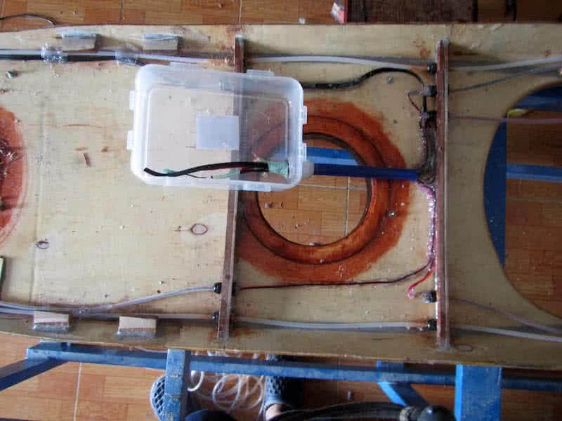
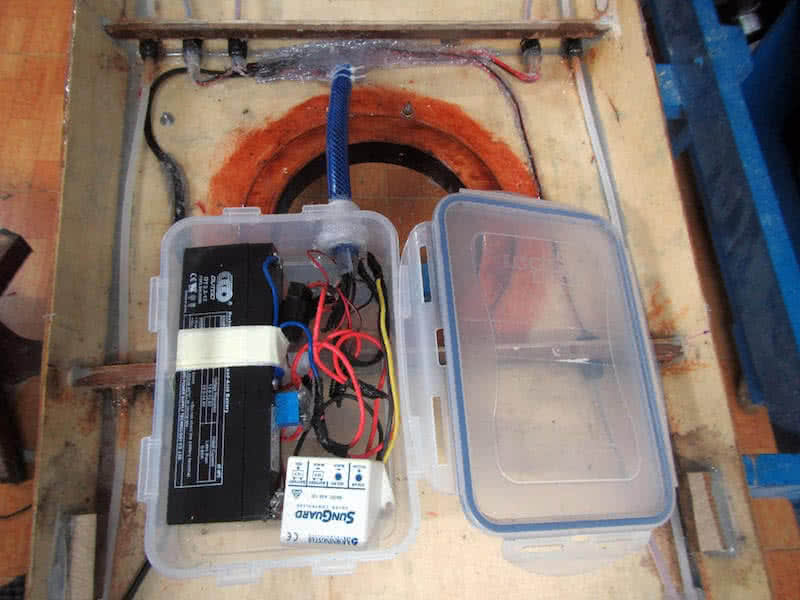
The two other pins supply power to the relay itself, when powered on (decided by the reed switch), the relay switches from NC to NO position, hence supplying power to the compass light. All wirings runs back to a central point: the plastic waterproof wiring box, which houses the battery, the solar charge controller, the relay… It took me some times to install all in the box, connect the correct wires, check if everything works!
The PowerFilm solar panel shipped with a long water proof detachable cable, so I run the cable from the central compartment to further aft where the solar panel would be located. This cable runs through a cable gland to exit the deck, ended with a waterproof connecter. It’s not very nice to always have this connector on deck, but it’s convenient to disconnect the solar panel and stored away when it’s not in need.
There would be another waterproof box (connected to this wiring box which would be rarely opened) which houses the 12V – to – USB and the 12V – to – AA charger, which could be usually opened to put your various devices in for charging (iPhone, VHF radio…) But that would be in another later phase of the project. It now time to joint the hull and deck parts together to form the final boat shape!