
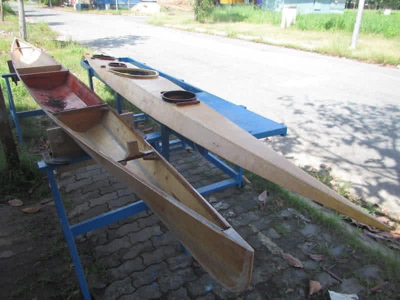
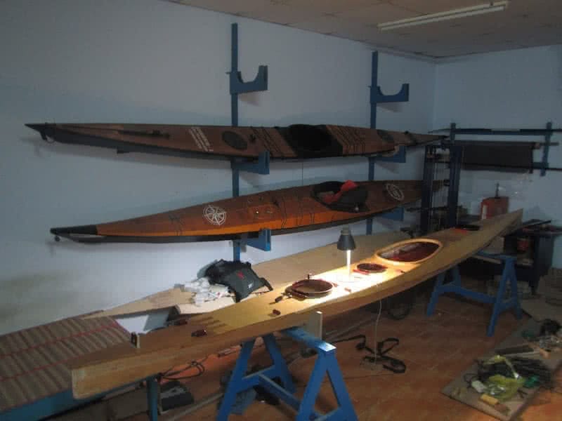
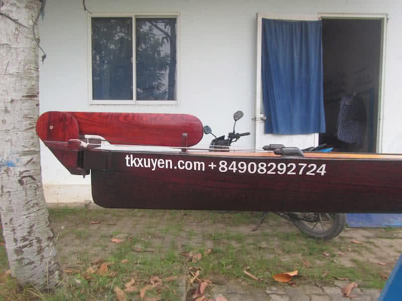
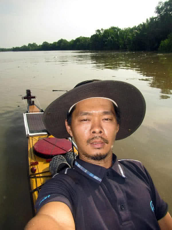
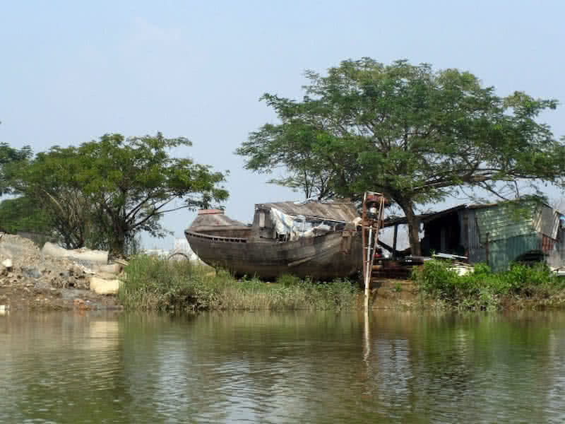
I’ve been thinking a lot about the design of my next build. Serene – 1 is a good kayak, she has proved that during my last 9 days trip crossing all mouths of the Mekong river. The boat shows her excellent abilities in various conditions, big waves, strong winds and turbulences, even when overloaded a bit above her designed displacement, she gave me a kind of confidence that I’ve never felt with any of my previously – built boats.
In the quest for an ideal kayak that perfectly fits me, I proceed to designing my next boat, Serene – 2. Some lessons learnt from my last trip are immediately applied: first is a transom – mount rudder. I’ve been into conditions of strong wind blowing whole day, and without a rudder to help adjusting the bearing, corrective paddling would be extremely fatigue. This will have an influential effect to all other designing considerations.
LOA is reduced to 17 feet, approximately 3 times the height of my body. Since maneuverability is entrusted all to the rudder, the boat would have a very full waterline length, very little rockers at two ends. I decide to reduce prismatic coefficient – Cp further to around 0.5; my sustainable speed in reality (paddling at sea with full load) is only around [3 ~ 3.5] knot. There is no reason to waste energy for a higher speed that I can not sustain.
Block coefficient – Cb is reduced to 0.35, this would improve directional stability a lot. In Serene – 1, this value is 0.45, which explains the boat directional un – stability on long distance. Transverse metacentric height – Kmt increased to 21 ~ 22 cm, roughly equal to most popular Greenland sea kayaks, and hence greatly improve primary stability. With Serene – 1, this value is 17 cm, enough to frighten any novice paddlers.

Until this second sea – kayak, I’ve been able to “read through” the hull designing parameters: Cp, Cb, Cm, Kmt, S, LCB, LCF, etc… interpret them correctly and know quite well what they do mean in real – world boat characteristics and performance. Many days out there paddling in various conditions and many hours spent on the whiteboard (a.k.a the Free!Ship software) make me feel very confident with my designing process.
The hull is shortened to 17 feet, reducing wetted surface area, but with minimum rockers, the waterline length is unchanged, also the designed – displacement is slightly increased to 120 kg, as 110 kg of maximum load is a bit under desire as pointed out in my last 9 days trip. Beam is slightly reduced from 45 cm to 44 cm, but both primary and secondary stabilities is significantly improved. I feel very pleased with this design so far!
Unlike my previous boat, the new one would have a curved deck. It is more difficult to build a round, curved deck, it is also harder to build hatches, compass cup, bungee cord anchor points and other parts… onto it. But with a curved deck, the boat will look nicer, less windage, and weigh less overall. Looking from above, it shapes exactly like a bullet, should I engrave a motto onto it: built like a gun, runs like a bullet
!?
The most important design decision is to increase the amount of deadrise. In my experiences with Serene – 1, the kayak has excellent sea – keeping abilities in rough conditions, something I didn’t feel with all my previous boats (e.g: the Hello World -3, which has a much flatter bottom). I would attribute that ability to the deeper V – hull, which offers quite a low primary stability, but should let you at ease in waves & turbulences.

Spent a considerable amount of time on optimizing the hull and deck lines. Some little more rocker at the bow, and less (almost square) at the stern. The hull is now a bit finer (less full), hence reducing Cp (prismatic coefficient) further into the [0.48 ~ 0.5] range, quite low indeed. Primary stability is also reduced a bit, with Kmt (transverse metacentric height) at about 21 cm, but the boat is sufficiently stable already.
Cb (block coefficient) is now reduced to 0.33, stepping outside the normal range of [0.35 ~ 0.45]. That is, the boat wouldn’t be very efficient at lighter load, e.g: with the paddler alone. But that would be fine anyhow, since the hull is optimized toward its full displacement, beyond 115 kg. And as confirmed with experiences in my previous kayak Serene – 1, the boat would feel a bit heavier, but more comfortable at full load.
Some other design considerations still need to be done, but they won’t be reflected into the 3D modeling, for the sake of simplicity: the cockpit size and shape, the size and position of the hatches, the rudder and rudder control, etc… Serene – 2 will have a 3rd hatch, or usually called: the day hatch, which locates right behind the cockpit, to store food for lunch and other frequently – accessed things during a paddling day.
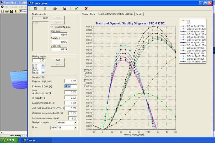
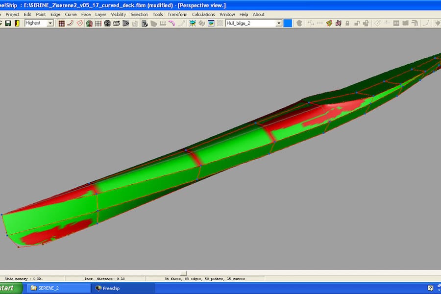
2nd image below: the stability curves for various loads: 85, 95, 105, 115 and 125 kg. The curves look exceptionally fine in my eyes, they won’t decrease until 50 degree of heeling angle, and the shapes of the curves closely resemble each other, showing a predictable behavior in hull’s stabilities. Almost done with the designing, I think, next is finding some free times to build the boat in the upcoming months.

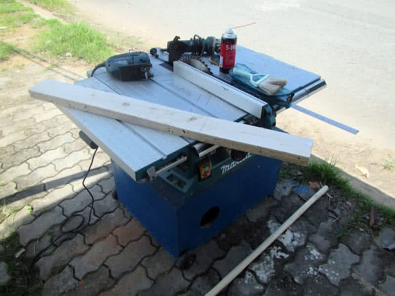
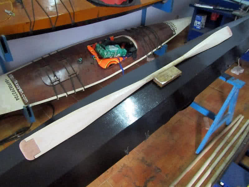
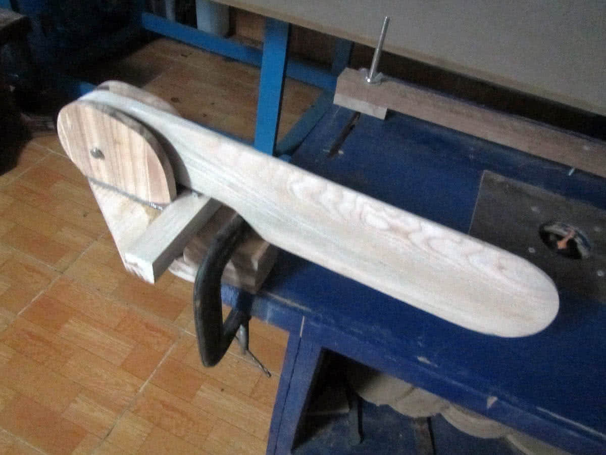
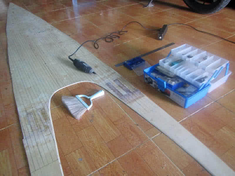
Still don’t have some free times to start my Serene – 2 kayak building yet, and all preparations (mainly materials purchasing) has not been completed. So I start slowly with building some other miscellaneous objects. First are the paddles. A typical WRC (Western Red Cedar) Greenland paddle weights around 0.7 ~ 0.8 kg. My two paddles, built with tropical hardwoods, though durable, weigh too much: 1.3 ~ 1.5 kg.
A lightweight paddle has very obvious advantages on long journeys, and I’ve been thinking about resolving this weighting issue. So I’ve decided to realize an idea which I’ve been having for a long while, in a tropical country like Vietnam, the best material you could use for a paddle is… rattan. Rattan is very lightweight, but it’s also very durable, flexible, and stiff, an ideal material to be used for building the paddle’s shaft.
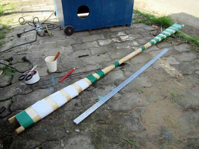
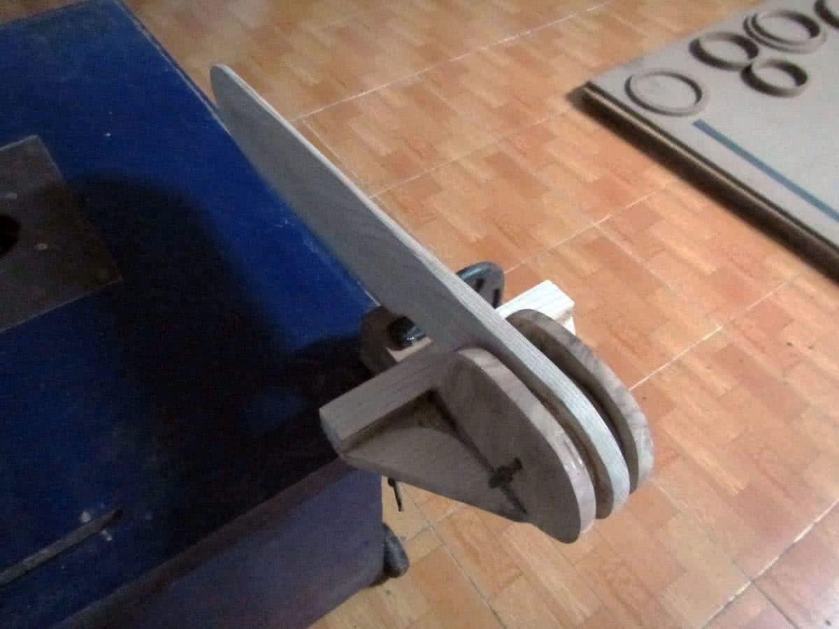
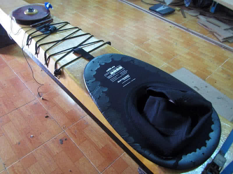
In order to keep weight to minimum, in combination with the rattan stick, I use balsa wood for the blades. Construction is quite simple indeed, the rattan stick is splitted into two halves at the two ends, and two balsa wood blocks are inserted to form the blades’ shape (see the 3rd image). Balsa wood is quite hard to acquire in Vietnam, I’d made the wood block from 6 small 5 – mm – thick balsa sheets, laminated together.
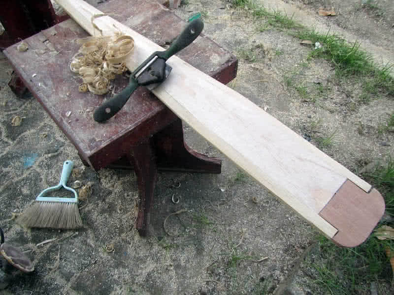
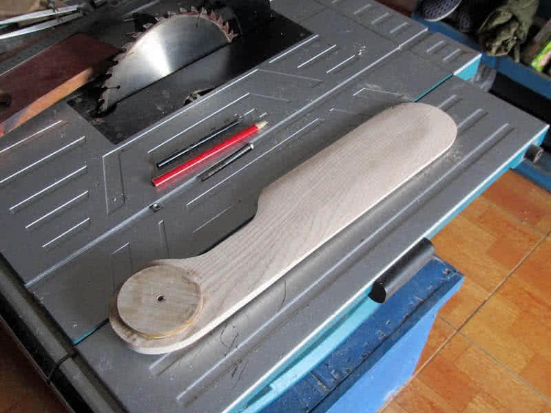
Next is the job of careful – carving down the blades’ shapes. The 4th image: empty spaces at the two ends of the paddle, that would be the places for two hardwood blocks in order to better resist against cracks upon physical impact. The paddle would receive a layer of glass to further strengthen the structure and to protect it against water. Balsa is too porous and without protection, it would takes on water in the long term.


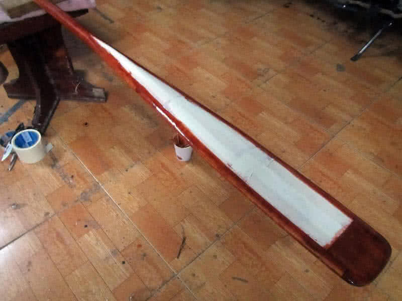
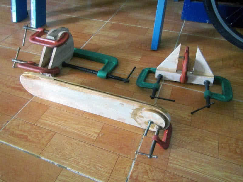
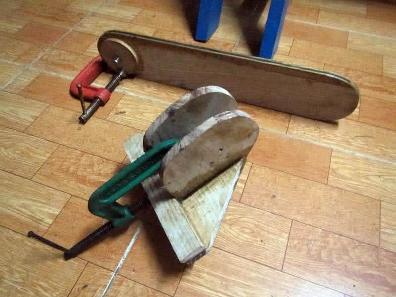
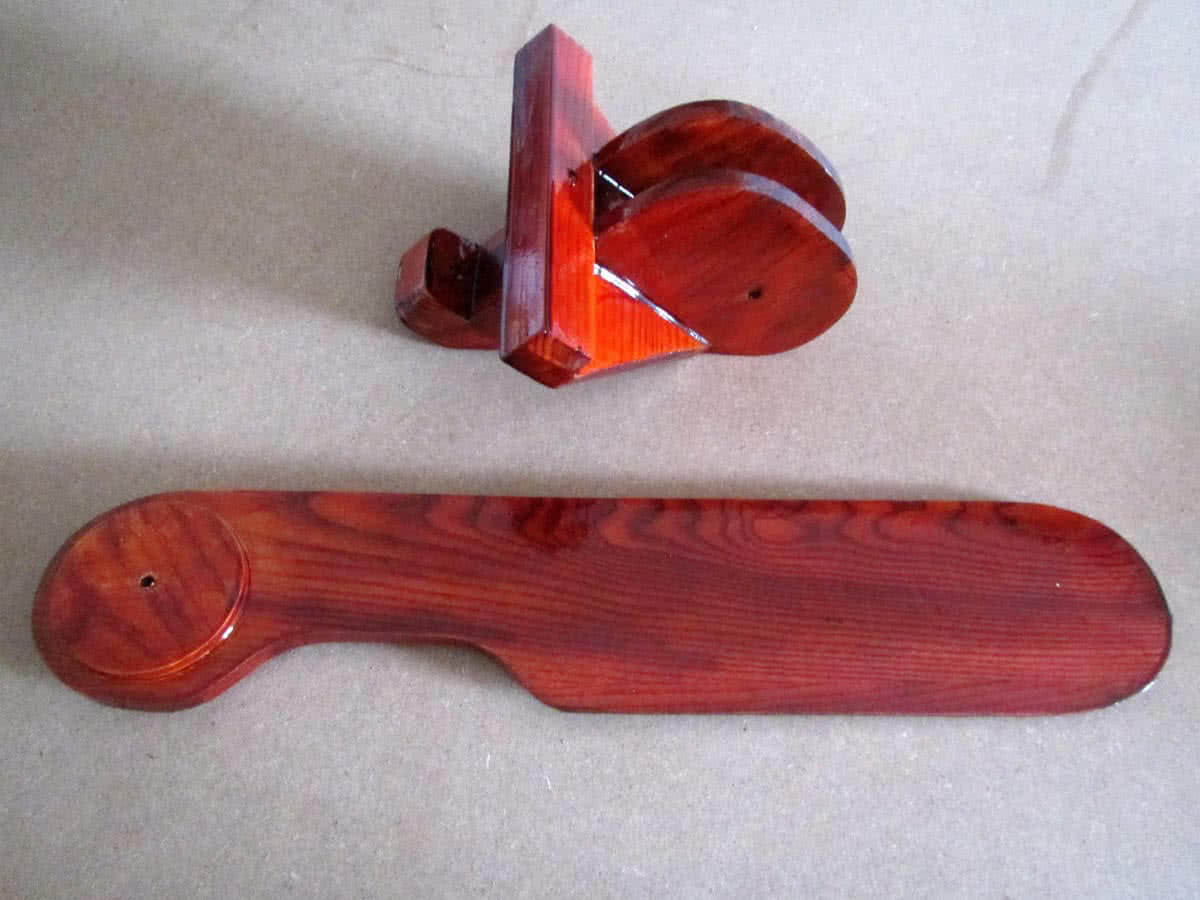
The first image: cutting two hardwood blocks to attach to the paddle’s 2 ends, 2nd image: scraping the paddle blades with a power planer and a spokeshave. 3rd image: the paddle takes its final shape, next it would be sanded, colored (stained with thinned epoxy), glassed then painted. The paddle would receive a layer of fiberglass all over the body, to waterproof the porous balsa wood, and to strengthen the whole structure.
This is only the first of two paddles I’d intended to build. A lightweight Greenland paddle would be my convenient, all – round thing to propel the boat with. But under some particular circumstances, e.g: very strong wind or current, I would need a more powerful tool, that’s why my next one would be a paddle of the usual Euro type, it would be also very lightly built, and has much smaller blades, around 50 x 14 cm in dimensions.
I’ve not yet to really realize which paddle type is better: Greenland or Euro, but thought that they all has their uses in different situations, and decided to build and use… both. Also, my paddles all has become smaller and shorter, their lengths now are around 1.85 ~ 1.9 m. My thought is that sea – kayakers nowadays are using paddles that are longer than needed (around 2.2 m), especially those going for long touring.
I made a terrible mistake, using the wrong duct tape to mask the paddle for coloring. A kind of 3M duct tape is so sticky that it’s extremely hard to be removed after having painted the paddle blades with colored – thinned – epoxy. I seriously scratch the surface while removing the duct tape (with a chisel) resulting in a very poor finish on one blade. The paddle would be perfectly usable, but not as good – looking as I’d expected.

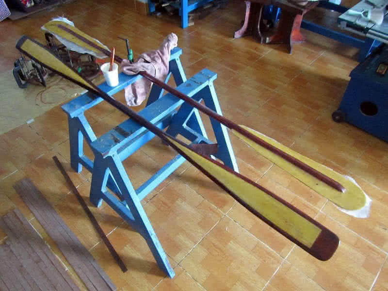
Finished with Serene – 2‘s first paddle, continue to the second one. This would be the pair of paddles, one Greenland style, and one Euro style, that I would use on the new kayak, intended to be slightly smaller in size, and much more lightweight compared to my previous ones. The Greenland paddle is not a typical Greenland one, it’s rather quite short with bigger blades, and the Euro paddle is not of typical Euro style neither.
As it is quite small compared to most Euro style paddles. It’s quite hard to justify my design decisions, but all came from my paddling experiences, that I would need a slightly bigger Greenland paddle for all – round paddling, and a slightly smaller Euro paddle to provide more power in “adversary” conditions. The second one would be lightly & simply built also, with that same kind of rattan shaft, and thin plywood blades.
1st image: the finished Greenland paddle. 2nd image: dry fitting the Euro paddle’s blades and shaft. 3th image: bending the plywood blades, I want them to be just slightly curved around the longitudinal axis, it’s just nearly impossible to bend the plywood around multiple axes, to decided to stay with the simplest blade design. After gluing the blades and shaft together, the paddle would receive a layer of fiberglass all around.
4th image: glassing the second paddle, next to it is the finished Greenland paddle, the pair of paddles near completion, they all need to be “trialled” soon, to evaluate their performances, and to see how they would behave in real world. Final weights, the Greenland paddle: 0.82 kg, the Euro paddle: 0.9 kg, not up to the “standards” yet, but quite near, that’s fine anyhow, as they’re very light (compared to my previous paddles).


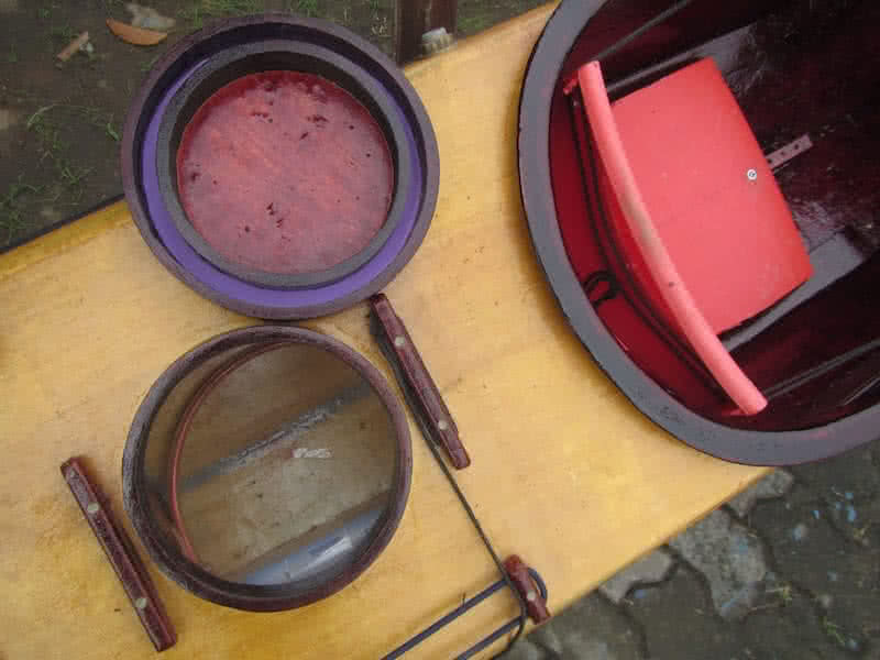
I’ve been thinking about kayak hatches over and over again. Starting from the very early days with my plywood hatches (in Hello World – 2, 3) which are obviously not watertight, to the Beckson hatches on my Serene – 1 kayak. The Beckson is very good, watertight and even air tight, but sadly that’s only true in ideal conditions. In reality, in multiple days trip, when mud and sand has get into, it would leak by a small amount.
The Beckson is not ideal hatch for kayak in my idea (for other purposes, it may be ok). The reason is that the hatches are built flushed with the mounting surface, and some inner elements are even recessed… When the water washes over (as always happened to the very low freeboard of a sea kayak), and when the O – rings are not properly lubricated, or when there’re some mud, sand inside the joints, water would leak in.
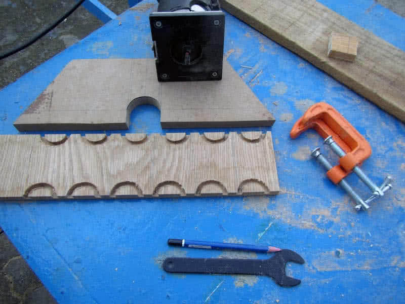
That’s why I decided to build my own hatches for this Serene – 2 new kayak. The idea is really simple: the hatches are raised a few centimeters above the mounting surface, and even when the seals are not too tight, that would suffice to keep most of the water out. Examine many sea kayak hatch designs, I’ve found out that simple thing, that the hatches should be raised (not flushed or recessed) above the deck.
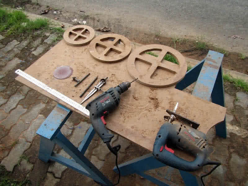
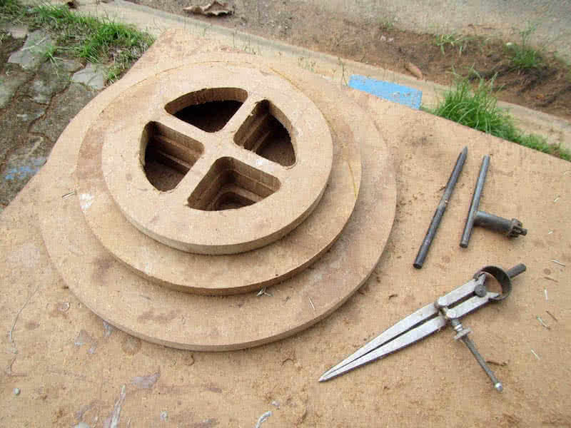
1st image: cutting thin (2.5 mm) wooden strips used to build the hatches. 2nd, 3nd images: the 3 MDF templates for hatch building: the rear, the front and the day hatch, sizes in diameter: 30, 25 and 20 cm respectively. 4th image: building the hatches’ coaming with thin wooden strips around the templates, each coaming consists of 2 layers of strips which bend easily around without cracks and without the need for steaming.

Had a major setback with making the hatches with wooden strips, the strips didn’t make perfect circles as I’ve expected, although they bend quite well, they’re off by small amount (e.g: 0.5 ~ 1 mm) here and there, and that’s an unacceptable precision for hatches, just a small gap and water could leak in. I had to abandon the method of making hatches using wooden strips, and tried to find some alternative ways instead.
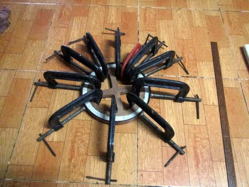
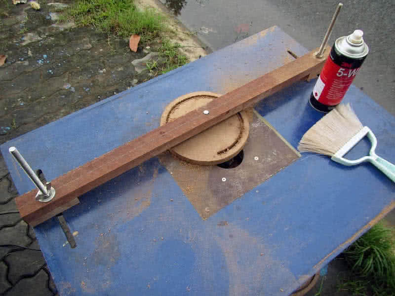
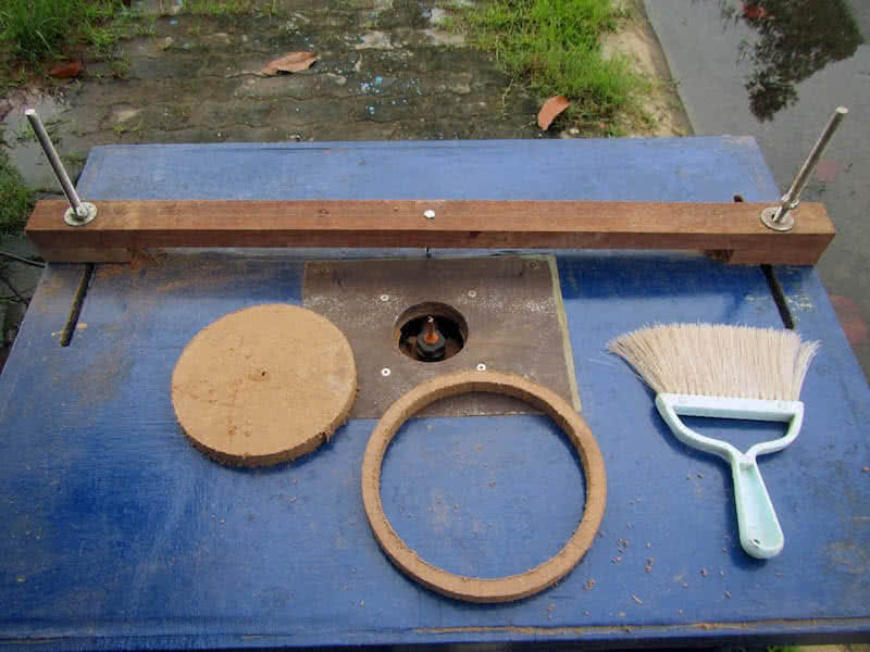
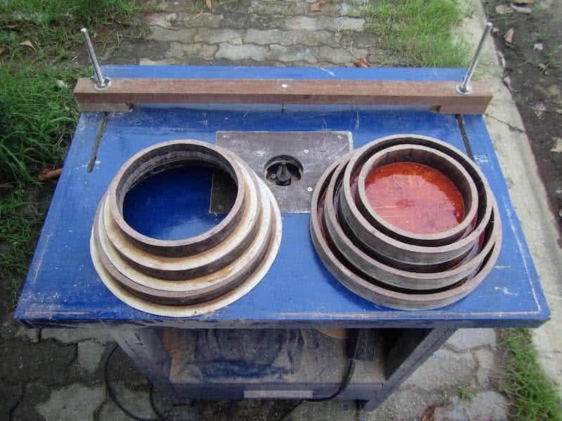
Finally, I resorted to cutting the hatches’ rings (lips) using my routing table. The home – built machine is made quite a long time ago, but this is only the first time making some serious use of it. It’s quick to make a circular cutting jig, as shown in the 1st image: the MDF “disc” would rotate around a pivot point that could be adjusted by sliding the wooden bar. The jig proved to offer good cutting accuracy (sub millimeter).
That’s really good, as I want very tight fits between the hatches’ rings, 3rd image: 2 rings cut, there’re still lots of it to be made. Using solid MDF as hatches’ rings has a serious down side: you would need to fill the MDF with much epoxy for it to be hardened, and waterproof, thus increasing the overall weight. On the other side, MDF is easy to cut into perfect shapes! Decided to go this way anyhow as I have few material choices!
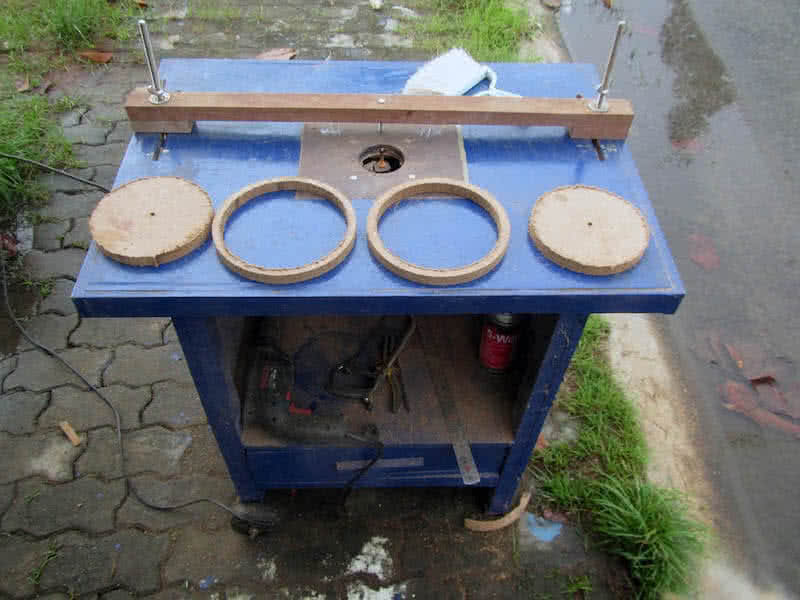
Last image: all the hatches’ rings is cut, 3 hatches, 3 lips per hatch, and 2 rings per lip (since they’re cut in 1.5 cm MDF, it requires 2 rings to form a 3 cm height lip), quite some work to be done, and too much of sawing dust too! And I’ve taken care on “quality assurance” to make sure that each ring is cut at its precise diameter. Though I don’t expect the hatches to be waterproof, it should be watertight as much as possible.
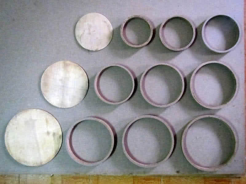
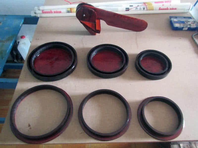
The structure of the hatches is nothing fancy, three tight rings nested inside each other per hatch, two belongs to the lid, and the other would be attached to the base (deck). First image: the 9 rings forming 3 hatches, filled with some thinned epoxy (about 400 gram of epoxy) to harden the MDF. This is not a very good way to make hatches (weight wise), but it would be just as heavy (or lighter) compared to plastic ones.
I was thinking a lot about the hatch locking mechanism. But finally decided to just use cords and cleats to tie down the hatches. The metal locks are too complex and fragile, unendurable to salt water. Tying down the hatches is much simpler and secured, and is easy to repair when something breaks. Between the 2 rings of the lid is a thin layer (about 3 mm) of epoxy (the softer, elastic kind) filled in to function as a gasket.
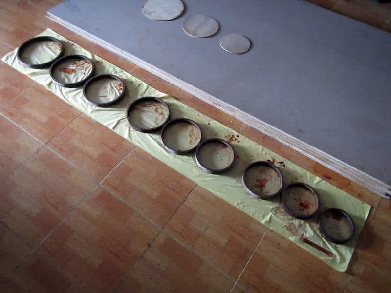
At first, I intended to glass in and out of each of the hatches’ rings, but the 9 mm – thick MDF walls have absorbed enough epoxy, and have become really strong (maybe more than enough, they’re now a bit too heavy), so there’s no need for glassing. The good thing is that once everything is assembled together, they fit very tightly, the lids and the bases, and the dark brown color is stained nicely too!
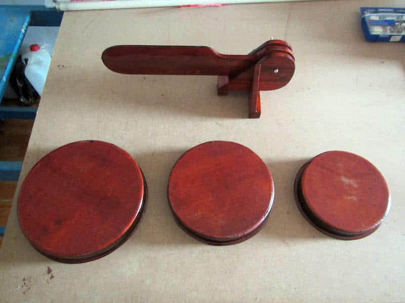
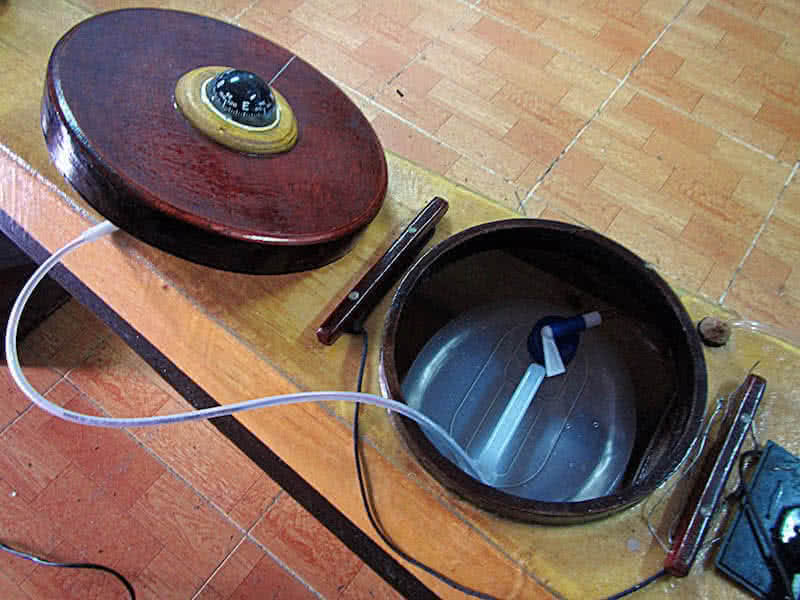
3rd image: the complete products, lids opened, 4th image: the lids closed. Once I’ll finish building up the kayak’s deck, the hatches would simply be glued on. Only the front hatch needs some special treatments, as the front deck is curved in shape. Also, the compass would be mounted right on this front hatch lid, to save deck space, and to simplify the building process. But that would be another later phase of this project.
Skeg, rudder or none!? It has always been an everlasting debate among the sea kayaker community. Some advocates using none, as getting the job done with your paddles alone would greatly improves your skills. While I partially agree to this argument, I also think that the argument only holds true on flat water only. When in turbulences, which could be extreme, you would need something to assist in tracking and steering the boat.
All my previous kayaks was using skegs. While a skeg wouldn’t help in steering, it would help a lot keeping the boat on a straight track when underway. Gradually, and especially in my last 9 – days trip, I realize that a rudder could potentially become a great benefit. You could pull it up to reduce drag (with a retractable rudder) and maneuver the boat with your paddle alone when it’s relatively calm, and deploy it down in turbulences.
Not only it helps turning your boat to compensate leeway, it’s also a way to have instant responsiveness, e.g: to deal with large chasing waves. So I decided to overcome my fear of complexity and build a rudder for my next Serene – 2 kayak. Yet, complexity is the reason most pro – skeg paddlers would give, to justify their favor for skeg. But serious sea – paddlers would agree, I think, that rudder outperforms skeg in most situations.
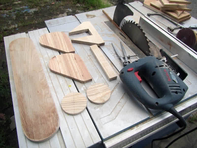
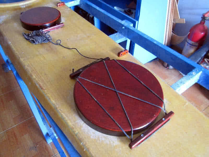
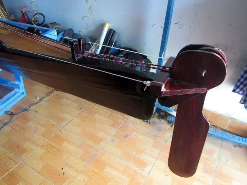
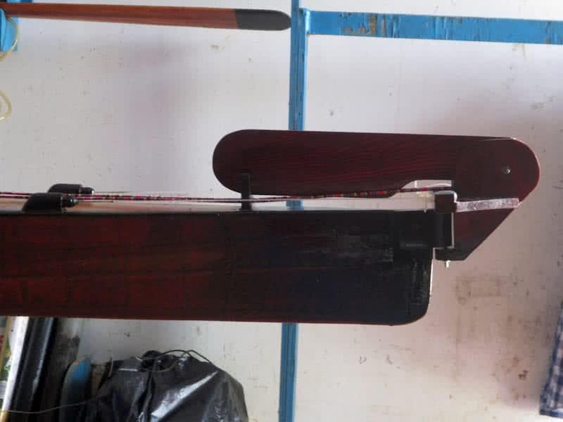
It’s not too complex (as it seems) to draft out the rudder’s parts on wood. 1st image: elements of the rudder, 2nd and 3rd images: gluing them together. 4th image: the rudder blade is (like they usually call) a high – aspect – ratio foil, 10 x 50 cm in dimensions. The 2 circular discs: ratchets for pulling the blade up and down. Now, I definitely think I could build a rudder that would work, both efficiently and reliably!
First image: assembling the rudder’s components, the rudder in its dropped down position, 2nd image: the rudder in its retracted position. Everything works smoothly as calculated, the blade could be pulled up and down by a pair of line running back to behind the cockpit (but that would be done later, when attaching the rudder to the kayak hull), with two circular ratchets glued on the two side of the rudder blade.
4th image: the rudder stained with colored – epoxy and then painted (with transparent PU – PolyUrethane). It looks so nice, the dark brown color with coarse wooden grains. The rudder control system is another complex problem, but that I would address it later on on the following phases of this building project, as I’m still hesitating between the two styles of rudder steering mechanisms as described below.
One style is the T – bar of those Olympic kayak, and the other is the normal 2 – pedals usually found on touring boats. The Olympic style is simpler, but it’s quite counter – intuitive as you would have to use the left leg kicking the bar to the right, in order for the boat to turn right. The 2 – pedals system is more user – friendly, you simply kick with the right leg to turn right. I also may use kind of a cross between the two mechanisms.
This is the first time I use a rudder, so many consideration and calculation have to be made. First in designing the hull, the hull should work efficiently and independently without a rudder, that is, it should track straight in most circumstances. Only under extreme turbulences that the rudder should be deployed, to save yourself from the extreme fatigue of one side paddling, or to have more responsiveness to the moving water.
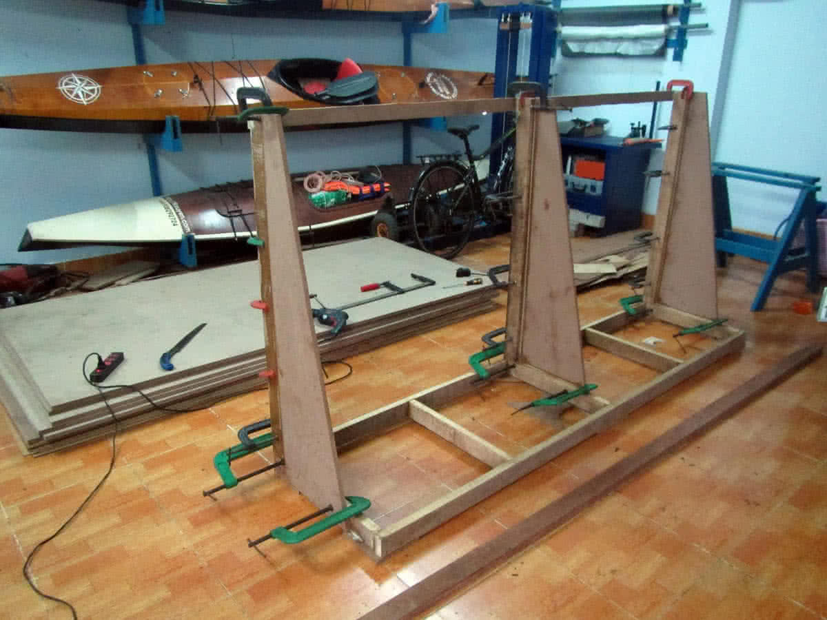
Not entirely related to this Serene – 2 building, but I would want re – organize my woodworking workshop a bit. My working place is quite small in floor area, so everything need to be stored neatly and tidily. Having quit some ideas, but would carry them out only one at a time, since I still have limited free time in the present. First is a shelf to store my plywood and MDF sheets (lots of them), and many other things.
The plywood and MDF sheets need special treatments, they could deform in shape or absorb moisture if stored inappropriately for a long time. The shelf would have two sides, the sloping side is for storing the sheets, and the other side is reserved for other things. The whole thing would be put on 6 small wheels so that it can be pulled and repositioned around the workshop, or moved just for cleaning the floor.
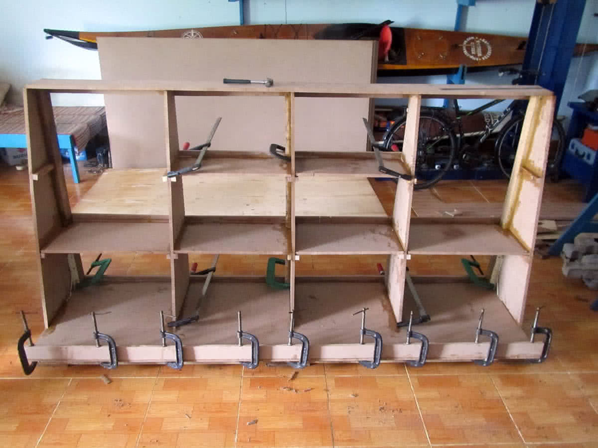
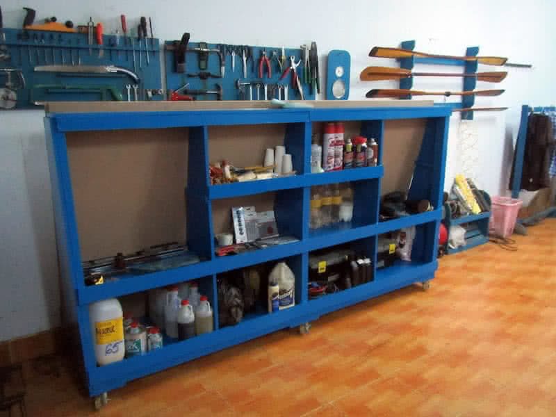
1st image: making the shelf base, 2nd image: the 3 supporting walls (to withstand the MDF and ply sheets’ weight, which could be very heavy). 3rd image: the shelf taking shape, 4th image: the completed and marine – blue painted product, ply and MDF sheets stored on one side (facing the wall). I need lots of shelf spaces to store various miscellaneous assets, which is growing to a unmanageable number.
Sometime, I’ve forgotten that I’ve purchased something just because there’s a huge pile of them around. The workshop looks very tidy now, having more spaces to store various things. It’s very important to keep thing tidy, uncluttered, as you wouldn’t want to waste time finding an item when needed. It’s now time to move on to the main parts of the project, I’ve been lingering around on other issues for long enough.
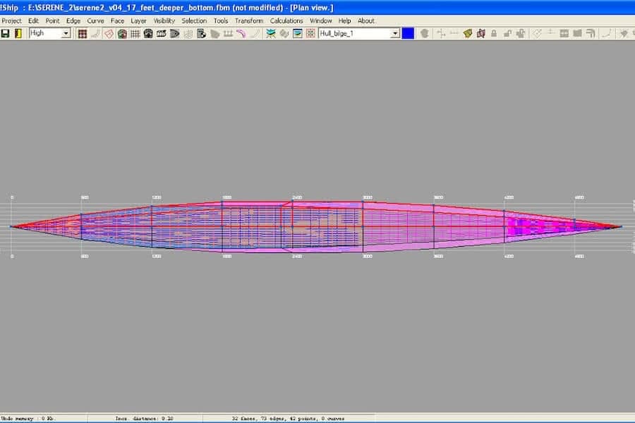
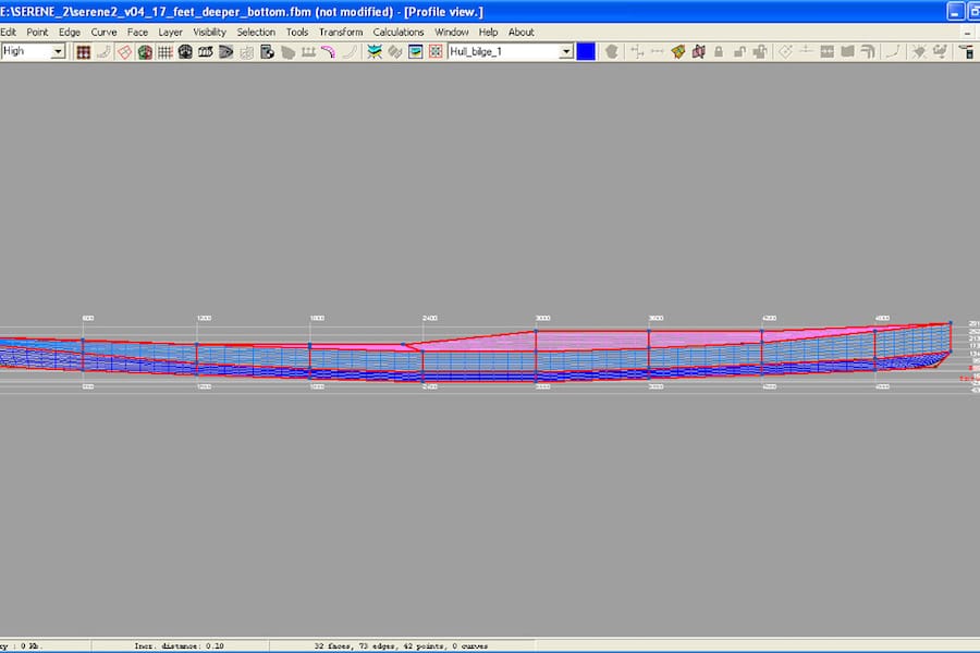
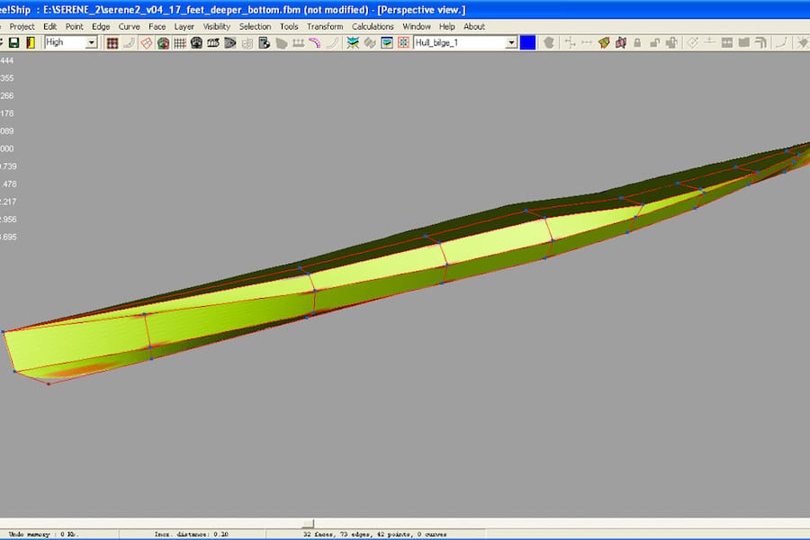
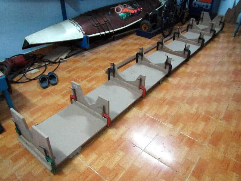
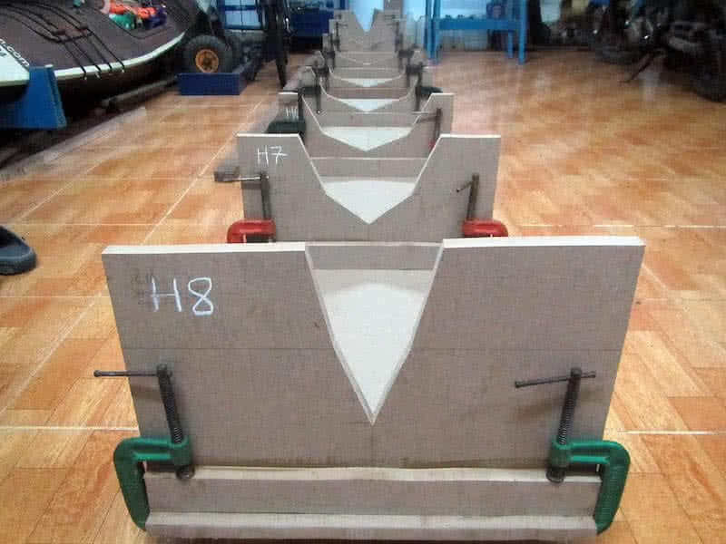
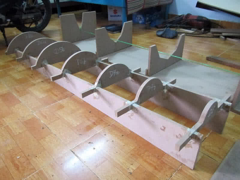
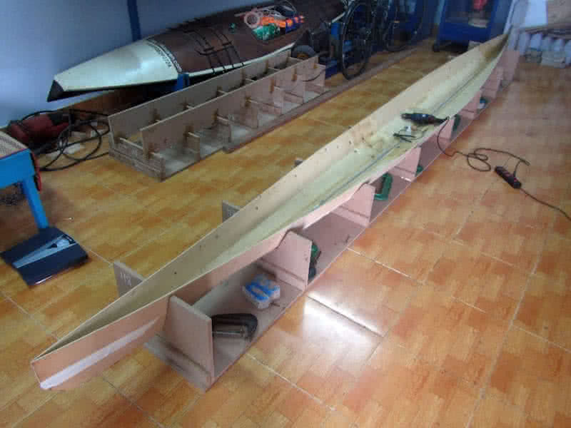
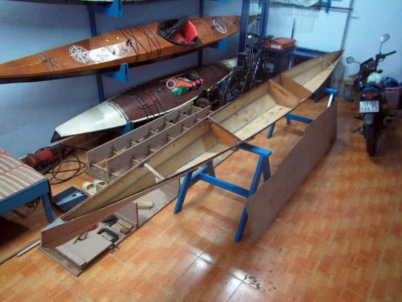
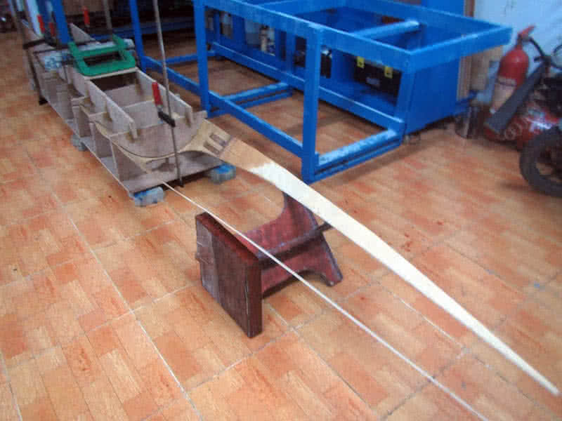
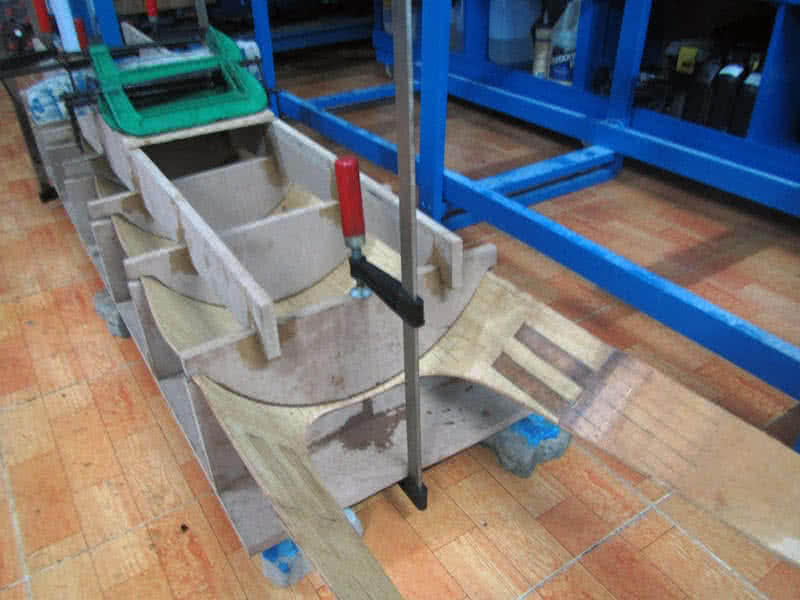
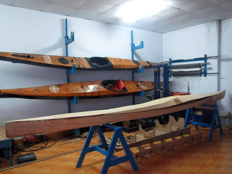
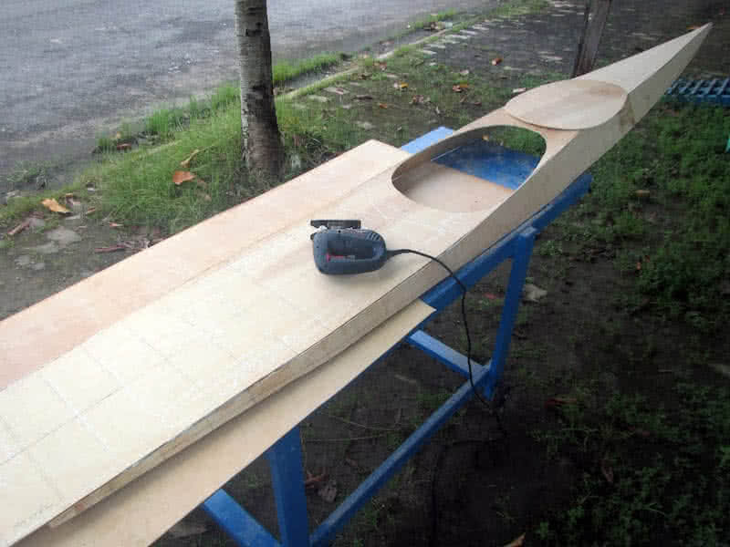
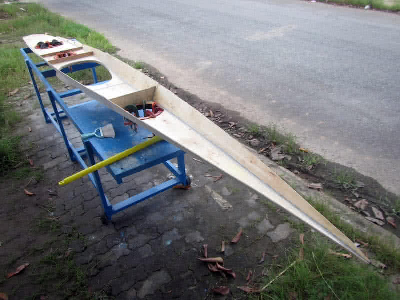
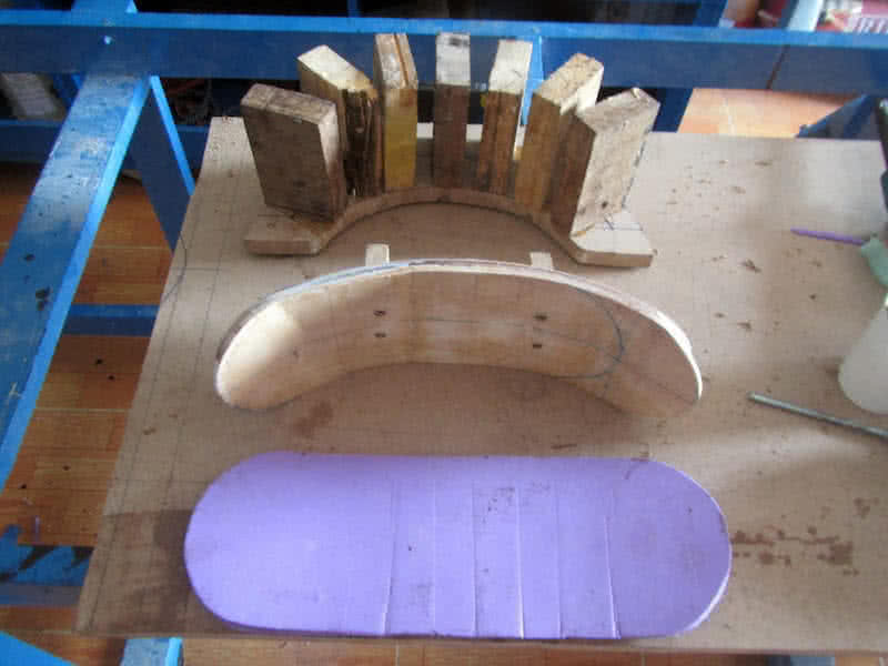
Simple thing that is done many times already, since the very first time I was building the Hello World -3 kayak, so there is nothing special about setting up the “female” frame for shaping up the kayak hull and deck. The stations (as called so by the software FreeShip) are placed evenly at an interval of 60 cm, there are 8 of them for the 17 feet (approximately 518 cm) hull. All is cut from 18 mm – thick MDF.
First image: the stations cut, second and third images: since the 18 mm – thick MDF I used is at the maximum that my compress – air staple gun could handle, I simple glue the stations on along a MDF board, each 60 cm apart. You can see the stations numbered, from H1 to H8 (from stern to bow). Fourth image: another view of the completed female frame, looking this way, one could see that the kayak hull is so slim. It’s so indeed!
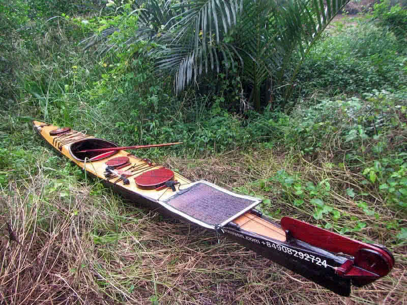
At 44 cm, this Serene – 2 kayak is just slightly narrower compared to my previous boat. Serene – 1, which was at 45 cm. One of the main reasons why it took me so long to start this kayak building is that, I greatly appreciate my previous boat’s abilities in rough water, it did give me a lots of confidence. I wouldn’t want to lose that very special capabilities along my design progress, while improving some shortcomings…
…That my previous kayak had had. It is a very good feeling watching the “female – molding” frame, which gives me a very first impression on how my future boat would look like. But the long way is still ahead, it would take much efforts in completing my “perfect sea kayak”! By the way, the “rule” for choosing a sea kayak hull is that: build / buy a longest and thinnest one that you could still find it controllable and comfortable!

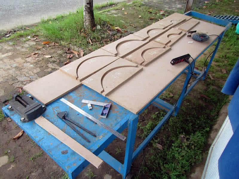
Framing for the deck is more complex than the hull, since the deck would be curved in cross section, it require torturing plywood to a considerable degree to acquire that shape. From my previous experiences with bending plywood panels, I decided to break the deck framing into 2 parts, one is female, the other is male in shapes, then compressing the plywood sheet in between using many G – clamps.
First and second images: cutting the deck framing stations, can see clearly that the upper and lower parts of the deck frame are cut from the shame plywood sheets. Unlike the hull’s stations, which is positioned at an interval of 60 cm apart, the deck’s stations are placed denser, one for every 30 cm. The deck plywood would be tortured between these upper and lower stations to achieve the desired curved shape.
Bending plywood, particularly the 4 – mm thich ply I’m using, could be a hard task (and currently I don’t have any 3 – mm or thinner ply readily for making the deck). More over, the plywood I purchased is not of very good quality, it could crack too easily. So I would need lots of tricks to get the job done: soaking wet the plywood overnight with water to soften it, using hot boiling water to soften it even more.
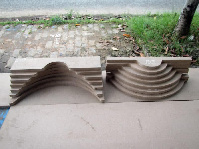
(Currently I don’t have any wood steaming device, and there’s no plan to build one just yet.) Another trick for bending plywood is making shallow cuts longitudinally onto one side of the plywood sheet for it to bend easier. Fourth image: the curved stations of the deck glued on. Now all jobs related to the framing is done, next would be proceeding to cutting and joining the bilges… the long and hard way is still ahead!
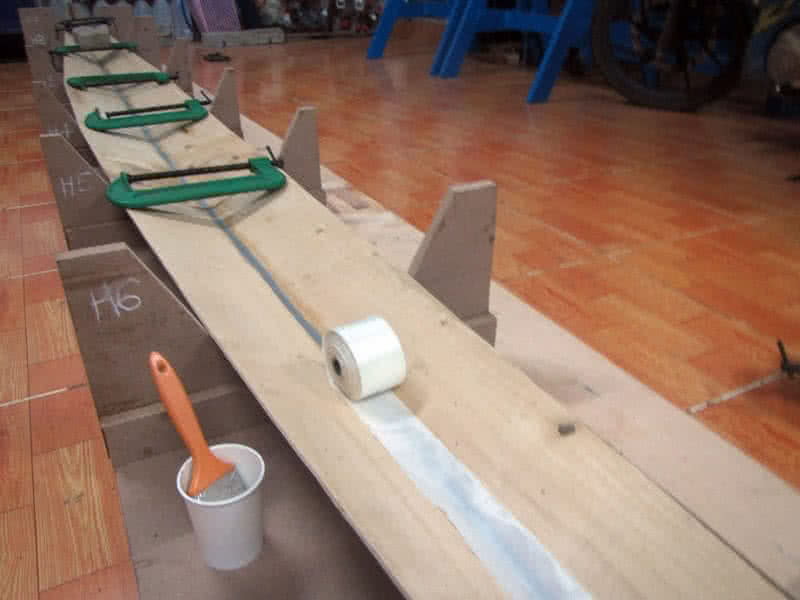
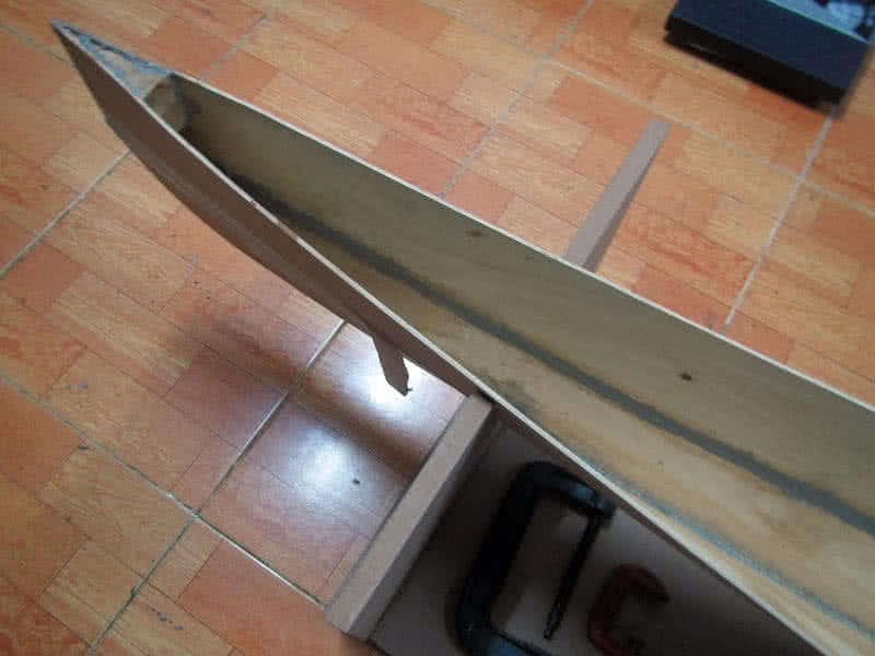
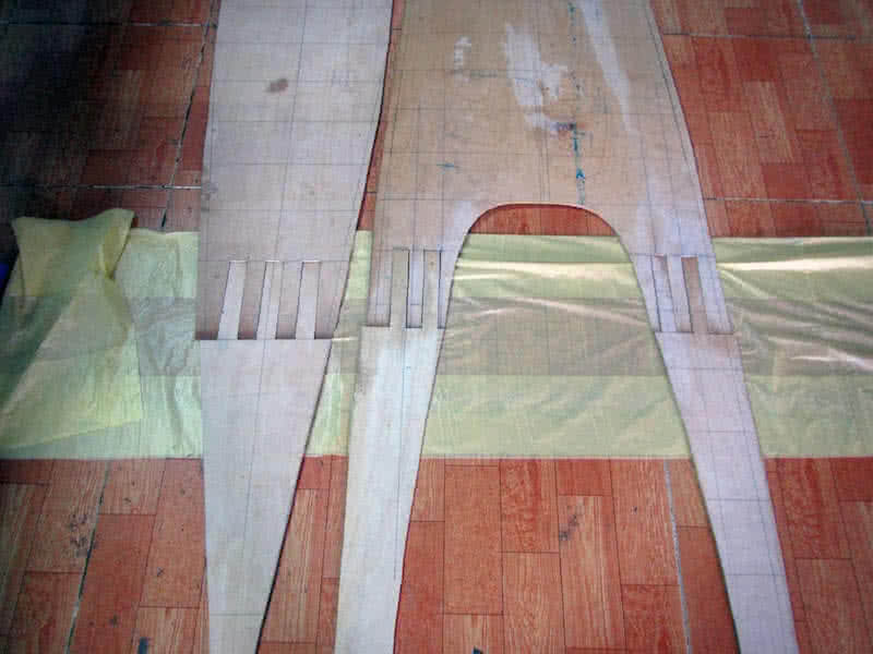
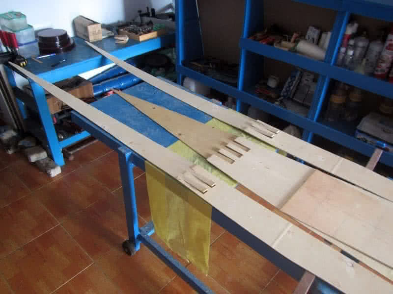
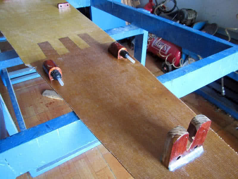
Proceed to cutting and jointing the bilges. This step is done quite quickly as I’ve now had plenty of experiences. I read the offset – table directly from the FreeShip software, then draw the bilges on the 122 x 244 – cm plywood sheet. For the 17 feet hull, there’re 3 pieces per bilges, and hence, 2 joints need to be made for each bilges. I clamp 2 plywood sheets together and cut the port & starboard parts at the same time.
It takes some little skills and experiences to make the joints perfectly fit with just a jig saw. And I still prefer the straight finger joints as used on my previous boat, they are simpler to cut, simpler to align and to make sure that the jointed bilges are in correct shapes. Too bad, my plywood is of too poor in quality, it’s so fragile, so easy to crack, so I have to take extra cares at this steps, or the “fingers” of the joints could break.
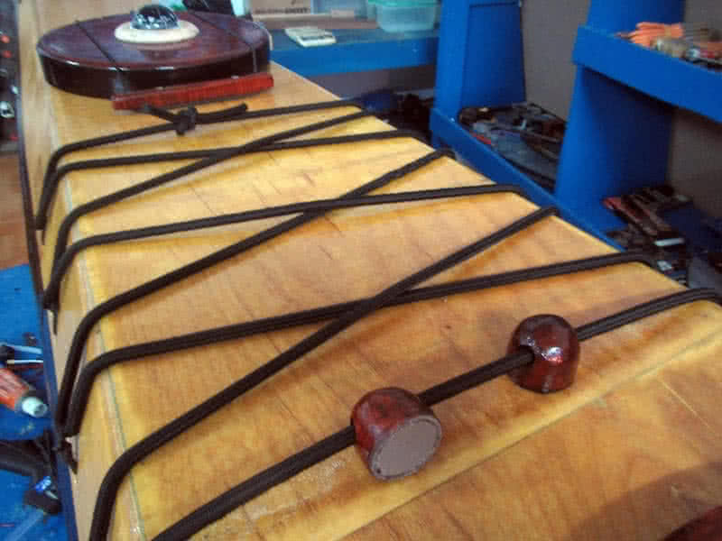
First image: transferring the lines from offset table to plywood boards (with the help of a cup of coffee, be careful not to make any mistake). Second image: all pieces cut, third image: the finger joints (no glueing yet). Fourth image: jointing the pieces together with epoxy (just use many weights to press on), then glassing them (the internal sides) with one layer of 6 – oz fiberglass.
Decided not to bevel the bilges’ edges, though beveling helps making tighter seams, my plywood is quite thin, so the seams wouldn’t be very perfect, they hardly could stay precisely edge on edge with each other (and beveling adds some more works to be done). With Serene – 2, I proceed with the hull first, then the deck, not doing them in parallel like my previous boat, as the deck part could be quite complex this time.


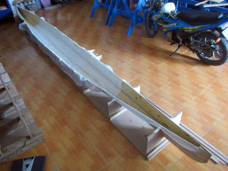
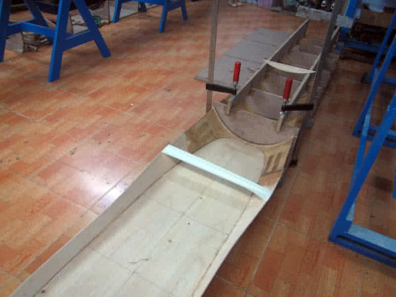
Fitting the bilges is quite straight forward. Compared to my previous boats, this time, due to more careful drawing and cutting, having a good shape, the bilges fit together pretty much better, there’s almost no gaps between them. It requires still some little fastening with wires, but not much, and some dots of CA glue (cyanoacrylate) to help the edges staying head – on. Then I proceed to filling the seams with thickened epoxy.
First image: the bottom pair of bilges fit together. Seeing them fitting so well to the molding frame, I decided to putty – fill and glass the bottom seam before adding the second pair of bilges (second image). I really appreciate my 2 – inches – width fiberglass tapes, they help the seams to be very clean and tidy (and hence less epoxy used). With out them, fiberglass cloth bias cutting would be a nightmare for me…
…As the kind of fiberglass cloth I’m using is not too good in quality. Third and fourth images: the second pair of bilges goes in, also very good fit, requiring little fastening. Due to the sloping sides of these bilges, filling the seams with putty could be tricky, as the thickened epoxy wouldn’t hold shape but flowing down slowly due to its viscosity. So, I apply a small amount of putty, then immediately cover them with duct tape.
This way, the epoxy would hold shape, leaving a good looking seam. After the epoxy completely cures (about 8 hours in my case), I peel off the tape. It’s so good a feeling to see your boat take its initial shape. I spend sometimes standing, watching the bow and stern, its full water line, its slim and sleek lines. Still many things to be done, but this gonna be my Andalusia horse on the wide wild wet water space!

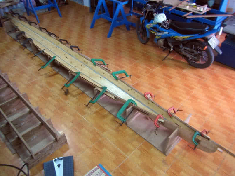
Finishing the fist step of forming the hull into shape, then filling the seams with putty and glass them with my 2 – inches fiberglass tape. The glass tape is my life saver, thanks to it helps again, that the seams could look neat and nice. To this day, I’ve acquired enough experiences and skills working with epoxy and putty already, so I’ve been able to mix the very precise (usually very small, e.g: 30 ~ 60 gr) amount required for each task.
Remember my very first days coming to boat building, working with epoxy has been a nightmare, that extremely sticky substance that messes and flows around. I have a very good feeling that everything is completely under my control in this build: the bilges fit tightly, the bulkheads fits very well, there’s no need to adjust here and there, the amount of epoxy and putty used could be estimated with quite an accuracy.
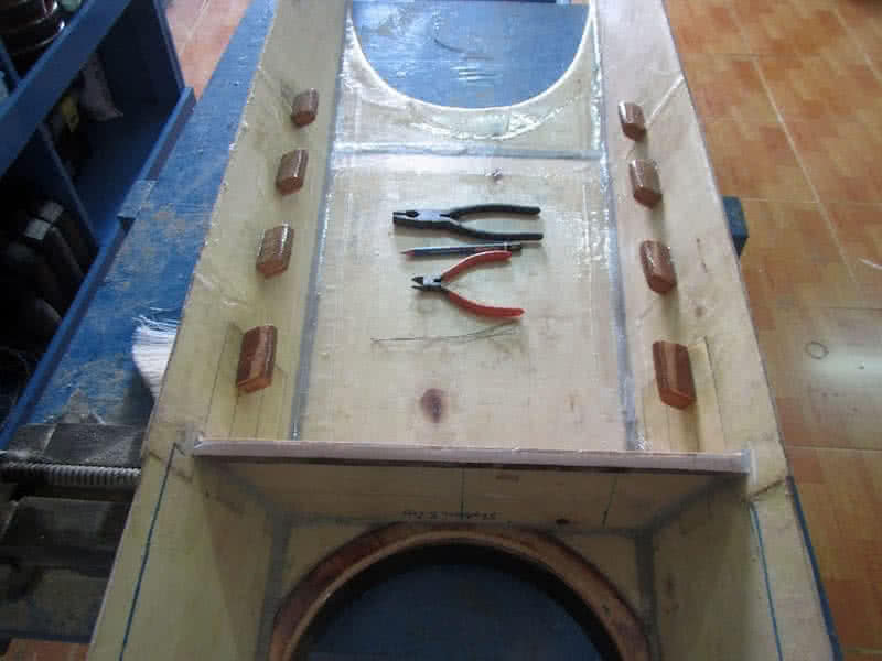
Second image: dry fitting the bulkheads, this time the cockpit would be slightly larger, to accommodate the bilge pump, and the rudder control pedals. Third image: fitting 2 prism – shape wood blocks at the two ends of the kayak, one at the bow for getting the pulling line through, and one at the stern to mount the rudder post. Again, very little epoxy and putty used, the wooden blocks add some saving to the final boat weight.
Fourth image: glassing the internal side of the hull, I’ve been thinking over and over again about this issue, do I really need to glass the hull internal side, consider the glassing seams are quite strong already. Finally, I decided to glass anyway, as my plywood is not of very good quality, it’s better to have some protection in the long run, with the cost of about 0.4 kg of epoxy (plus the fiberglass fabric) added.

After the internal side get glassed, goes in the gunwales (American English: the sheer clamp), port and starboard at the same time. The gunwales are very thin strips of wood, 2.5 x 1 cm in cross section, and are bevelled at 45 degree all along its length (they are bevelled with my table saw), later the bevel angle would be adjusted along the boat hull (with an angle grinder) to better accommodate the deck.
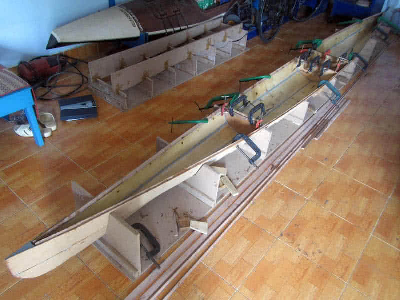
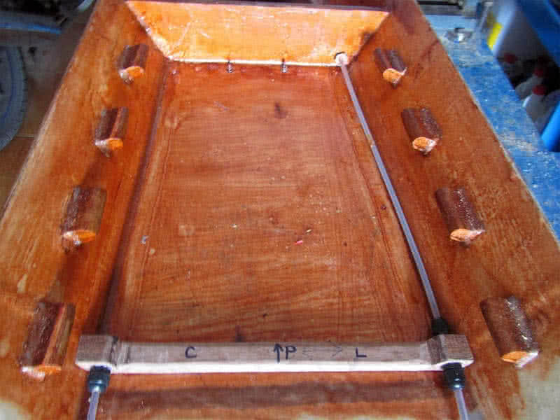
Second image: the 3 bulkheads, the small compartment right behind the cockpit would be the place of the day hatch, to store food, drink and other various things you would frequently need during a paddling day, and could be accessed while afloat (still sitting inside the cockpit). For other hatches, you would need to beach the boat in order to access them. Third image: the bulkheads are filled with putty at the joints and glass on one side.
Fourth image: triangle blocks of wood use to reenforce the joint between the gunwales and the bulkheads. With no need for nail or bolt, the triangle wooden blocks link the squared corners, this way, the kayak’s “frame” would be significantly stronger, stiffer, a simplest, yet elegant solution. There’re two additional thwarts installed near the bow and stern to strengthen the boat’s overall structural stiffness.
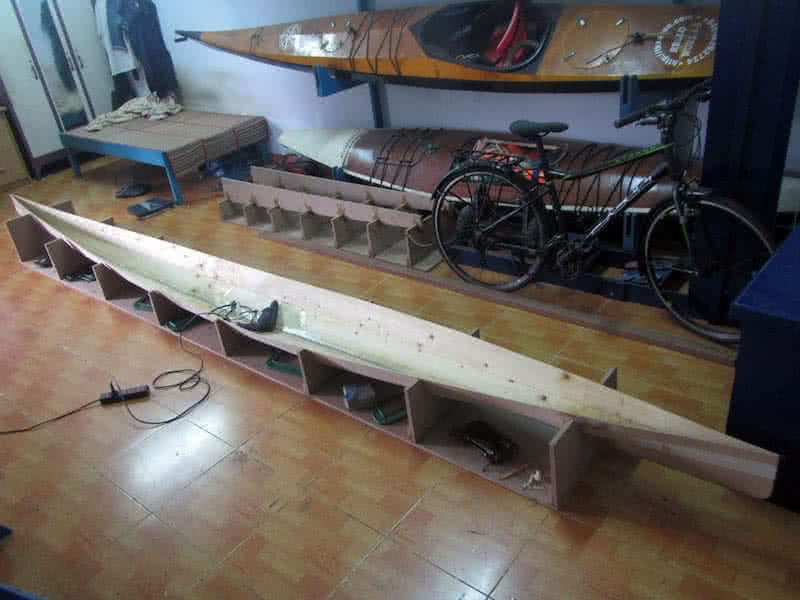
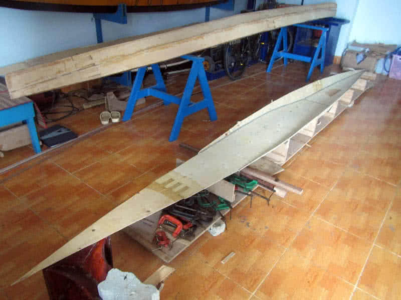
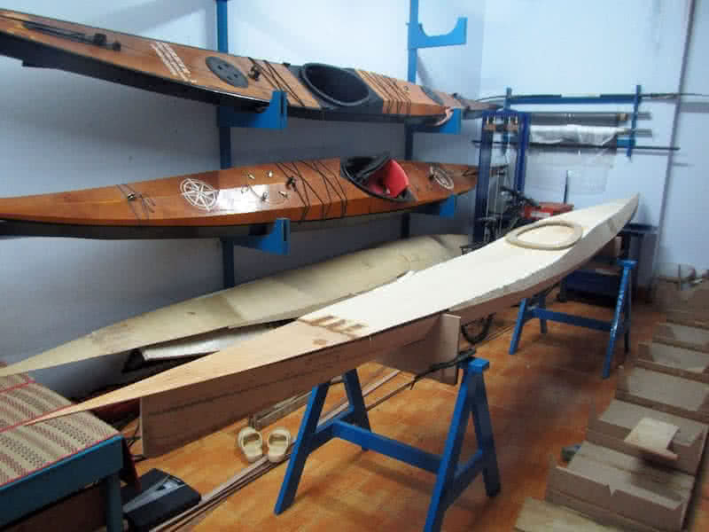
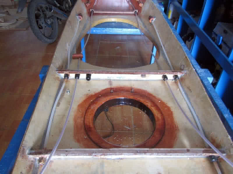
Completed most jobs with the hull (there’re some more on the external side of it – puttying, glassing… but that would be a later phase of the project), now moving on to the deck part. It doesn’t seem immediately apparent, but the deck part is a more complex part, compared to the hull, it would house many things: the 3 hatches, the compass, the rudder pedals and control lines, the anchor points for bungee cords, etc…

First image: the basically completed hull, put aside, now working on the deck part. Compared to the hull, which is… simpler and more well defined in term of geometrical shape, the deck is just loosely draft out in overall shape, it’s cut slightly over size, so that when fitted together with the hull, it would be trimmed to match. The construction is also more complex, due to the rounded shape of the forward part.
I had a hard time thinking about the cockpit and spray skirt size. A width of 44 cm is almost the minimum that could fit a cockpit, that in turn, could fit the smallest spray skirt sold on the market. Ready – made spray skirt (e.g: Snapdragon, Seals, Sea to Summit…) usually have 44 x 75 cm as the smallest dimension, other than that, you would need to order a custom made one, which is an expensive and complicated process.
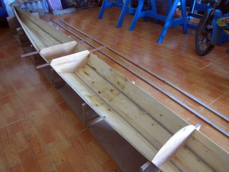
Second image: drafting out the deck shapes on plywood. Third image: jointing the pieces together, again with those simple finger joints. Fourth image: the two main “components” composing the deck, the aft (far, left), and the front (lower right). I slightly bevelled their edges at places, so that they could fit more precisely together. The white duct tape: pin down the parts so that they’re correctly symmetrical along the longitudinal axis.
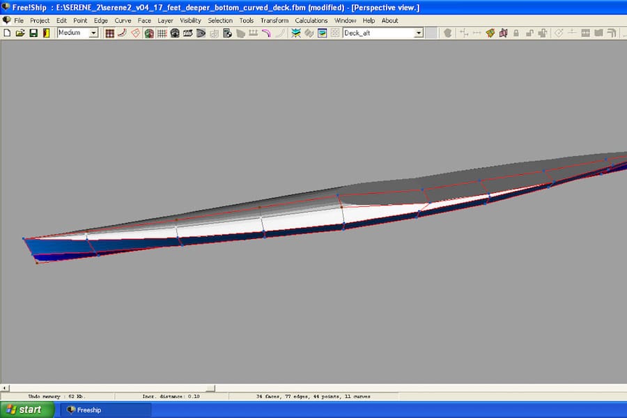
Next is the very important job of torturing the deck into rounded shape. By now, I’ve realized that there’s too much curvature on the molding frame, and I wonder if the plywood could bend that much to make a very curved shape, only experiment would tell. In order to help the ply bending well, I would make many longitudinal cuts on its internal side, then wet it completely overnight for the wood to become more flexible.

With my Dremel – Multi – 3000 tool, I made lots of parallel cuts onto the deck internal side (see the first image), the cuts are about 1.5 cm apart, and about 1 ~ 1.5 mm deep. Those are not very deep cut, since the plywood is only 4 mm (3.75 mm to be exact). Then I soak the deck with water thoroughly, for the ply to be softened, then put it into the frame and press it down… with my body weight (just sit on it).
With the extra help of some clamps, I press it down, little by little, don’t be too quick, just do it very slowly, then the plywood bends nicely into a perfect curved shape! There’s some minor cracks on the edges, but that’s not too important, cause those parts would be trimmed away when the deck would be glued with the hull. Second and third images: you could see how well done the curved deck is!
I let it there overnight, waiting for the water to vaporize, then apply some thinned epoxy onto the deck internal side, I also apply a few glass tapes at some places, that way the curved deck would hold its shape once released from the molding frame. Next would be puttying the rear part of the deck onto the forward part, a simple and straightforward job, then again, glassing the seams with my beloved fiberglass tapes.
Joining the fore and aft parts of the deck is quite simple, though it required some wire fastening to put everything under order. FreeShip (the boat design software) strangely generates a slightly abnormal curve around the cockpit (had I made some mistake, or didn’t use the software in a correct way?). So I had to manually draw the line by hand, guessing at some places, resulting in not a very good fit.
A major setback in the building progress, the curved deck didn’t come out with my expected quality. After released from the molding frame, the deck slowly bend back from its curved shape, especially amid of the boat, off from the desired geometry by 3, 4 cm (first image). That’s really bad… I made a hard decision to discard the rounded deck, and build a hard – chined one (like my previous kayak) instead!
I had an uneasy feeling, lots of work has to be redone, cutting and jointing the deck’s bilges (second image), setup the molding female frame. I took this chance to modify the deck design a bit, raising the aft part by 1 cm, to better accommodate the rudder control lines. A hard – chined deck doesn’t look as good as a rounded one, but it’s easier to build, easier to install other things, and it would fit with the hull much better.
Third image: forming the deck shape, the geometry is so simple that it doesn’t need any wire – fastening, just some CA glue here and there to fit the bilges together, some duct tape on the outside, then putty onto the inner seams. To save weight, I only glass the deck internal side at the cockpit area, where it could be potentially exposed to water. However, the deck would receive a glassing on the external side later on.
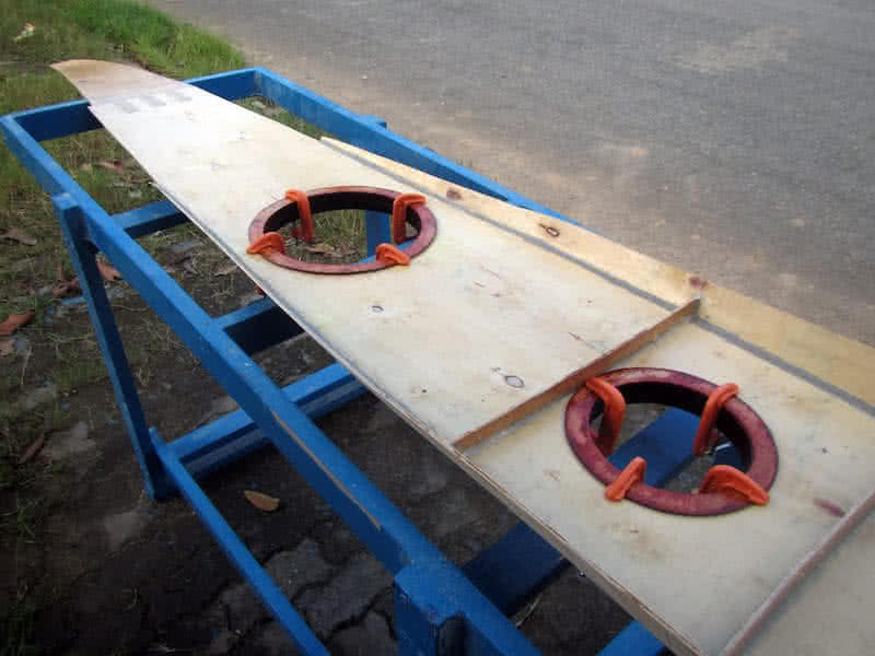
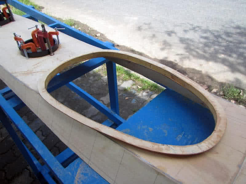
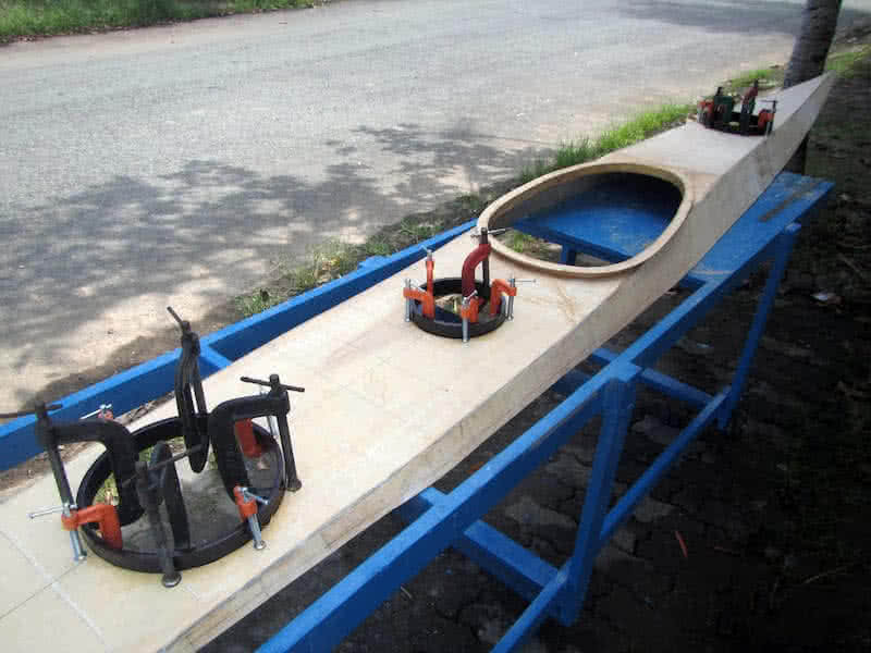
Fourth image: dry fitting the deck and hull… perfect fit! No adjusting, no fastening, no compressing would be required, just fit them together, then trim the edges! In the image, top of the cockpit area, we can see the cockpit coaming template (cut from MDF). That would be a frame for building the coaming lip and ring around, measured 38 x 64 cm in internal dimension. The external dimension would be 44 x 70 cm.
Continue working on the new deck! The deck has 3 bulkheads of its own, corresponding to those of the hull. The two rudder control lines would run inside plastic tubes, which run through these bulkheads via waterproof cable glands. But that would be later, first is installing the cockpit coaming, which is just a thin plywood strip bending around a MDF frame. The coaming lip is also cut from plywood.
First image: you can see my beloved Fein Multi Master, the renown oscillating tool. Often when I have to cut or do other tasks in tight corners or in positions that are inaccessible or inconvenient to other reciprocal tools, this Fein is my last resort, and it’s always been very helpful to me. Here, I need to trim the already installed, but wrongly – sized bulkheads. Also, really love the tool’s Germany quality.
There’re some other tasks which are not reflected in the images here: fairing the hull and deck’s external seams, then glassing them with my fiber tapes. It’s not until now that I could comprehensively master the skills working with epoxy and glassing, using just the right amount of them. But also, I also gave up the idea of a kayak that’s as light as possible. For a training, exercising boat, lighter is of course better.
E.g: 15 vs 20 kg is a huge different, cause it’s much easier to launch and retrieve the (almost empty) boat for every training sessions. But for an expedition boats, a few kilograms doesn’t make much difference, since a loaded kayak weighs as much as 110 ~ 120 kg, with that mass, you can’t carry on your back anyhow, so a few more kilograms added would worth the value of a stiffer, more durable boat prepared for long journeys!


Gnstalling the cockpit coaming and hatches is quite straightforward: the fore and aft hatches, and the day hatch. Then I bevel the deck’s jointing seams (the external side) a bit, as well as the cockpit coaming, the seams need to be curved in order for glassing to go on well. Glassing the cockpit coaming could be a little bit tricky, as the fiber fabric should wrap around and cover both the internal and external sides.
Talking a little bit more about jointing the seams here. For the seams to be strong, I follow these 3 steps: first is priming the seams with some epoxy, then when the epoxy has not cured, apply the putty. Putty has lots of viscosity, so it won’t penetrate well into the plywood, that’s why we need epoxy as primer. And once the putty has only half – cured, I apply the glass tape. That way, the seams would be very strong.
First image: fitting the hatches. The hatches’ bases would, from beneath the deck, go through the cut – out holes, they serve as reinforcement rings around. Since the hatches’ bases and lids are of the same height, going through the deck would leave a small gap (about 4 mm) between them. That would be the place to pour some epoxy in, the type of elastic, softer epoxy which functions like the hatches’ gaskets.
I didn’t glass the internal side of the deck, just some fiberglass tapes at the seams. Instead, the deck would be glassed on the outside, which should offer better protection against water. The internal side only receives a very thin layer of epoxy coating. The external glassing would slightly overlap with the hull (about an inch), to better strengthen the deck & hull joint. It looks like basic jobs are done? Actually there’re still lots of works ahead!
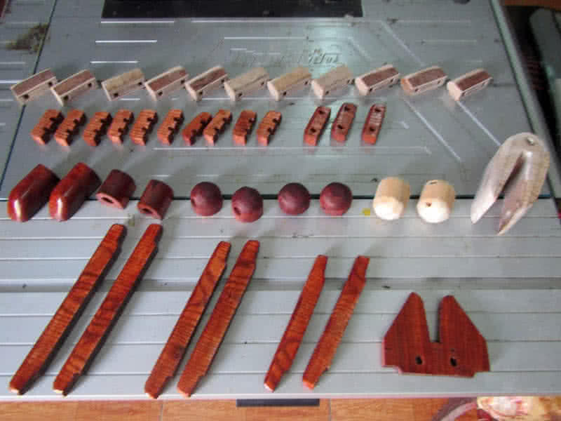
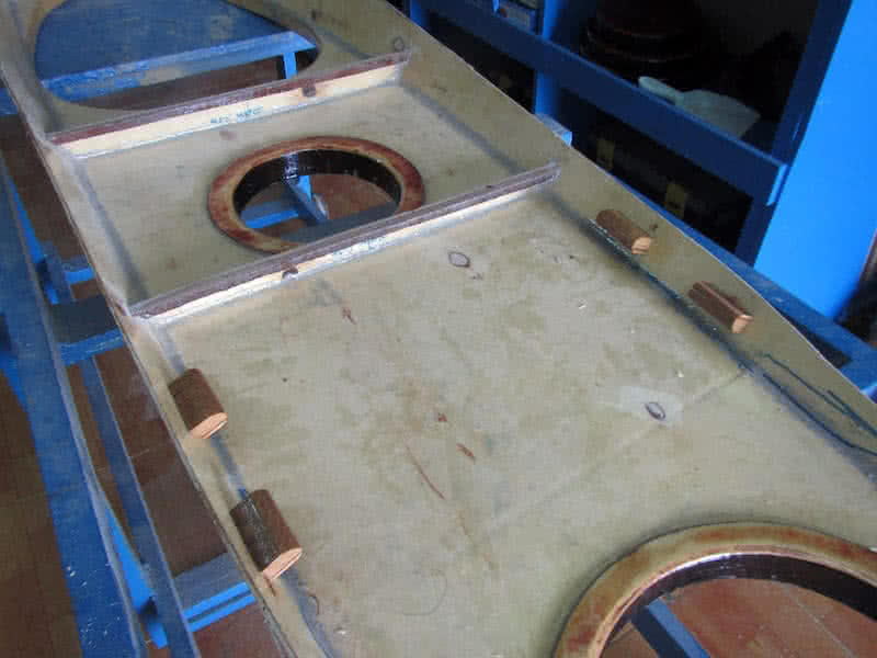
There’re quite a lot of works required on the deck. First, I need to make various small wooden parts: the bungee cords’ anchor points (14 of them), the cleats (6) used to tie the hatches down, the rudder post, wooden balls for line pulling, etc… all is very “small” wood working, you would need to work on parts that a just a few centimeters in size, an ugly type of work which I don’t like, since I don’t really have skillful hands for that.
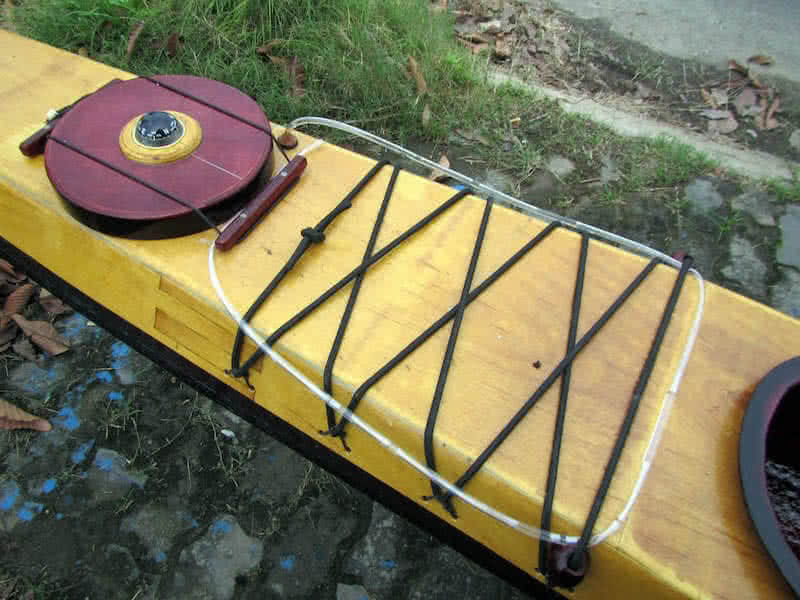
Second image: various wooden parts. First image: cut half – curve grooves for making the bungee lines’ anchor point using my router. The bungee would loop through that grooves, going from the external side, through the deck, then back to the external side again. There’re 14 anchor points like that to be installed, 8 around the cockpit, 4 on the aft deck, and 2 on the fore deck. Here, I learn to cut with the router following a template.
Third image: fitting the cockpit anchor points, the installation is quite simple and straightforward, the wooden blocks are glued on, with steel wire fastening through the holes, later some little putty would be filled in the jointing edges, and maybe some glassing too. This way, the bungee cords’ anchor points are made so simple, easier to implement, not the same nasty, clumsy way as in all of my previous boats.
Next in installing the rudder control lines’ tubes. Those are 6 – mm diameter (4 – mm internally) plastic tubes that run from the cockpit, through the day – compartment and aft compartment to near the stern, running through 4 cable glands on the way for each tube. The installation is quite messy, as I was using too much silicone glue, in an anxiety to assure that these cable glands would be completely waterproof.
First image: the 6 – mm diameter plastic cable glands, with a cigarette lighter for size compare. These cable glands are used at various places on my Serene – 2 kayak, but primarily used for running tubes, cables through hull. With proper installation, they should be waterproof, with the extra help of some silicone glue. Second image: the rudder control lines’ tubes, running through 4 cable glands each all the way from the cockpit.
All electric cables on my boat would be placed inside plastic tubes, to maximize their waterproof capability. So they would also need some cable glands to run through the bulkheads. But that would be the next step of the project. Now, just all things rudder related! Third image: the rudder pedals, simple pieces of wood that could be rotated around hinges. Since all these parts are quite near the compass…
So the hinges, the screws… are all made of brass. I had a hard time finding these brass parts, cause most available on the local market is actually made of steel, just copper plated. It’s quite weird carrying a piece of magnet around the shops, to verify that they’re actually non – ferromagnetic, but I have to really make sure about that! For the compass, I would just used the same type as in my previous boat.
Though a simple and cheap compass, it has been verified (in my last 9 days trip) to work correctly and reliably. Before installing other parts, I slightly sanded the deck, applied some colored – thinned epoxy (for color staining, this time, the deck also has a yellow color like my previous boats, but much a lighter shade). Next would be glassing the external side of the deck, before fitting many other parts onto it.


The deck is stained in a light – yellow color, compared to my previous boats, this kayak would receive a much lighter color scheme. Light, bright color would reveal more the defects on plywood and my building mistakes, but I don’t really care about that anymore, as soon as the faults are not too obvious. Then a thin layer of glass throughout the deck (first image). Next comes various deck fittings.
First are the cleats used to tie down the hatches’ lids. These wooden cleats are glued on, then bolted down with 2 small bolts for each cleats. I carefully fill the bolts’ holes with epoxy, then paint the internal side with some epoxy to prevent water leaking in. Tying down the hatches’ lids with lines is not a very handy way, but it’s simple and very secured, compared to other complex locking mechanisms.
Last image: the rudder control lines’ tubes exit the deck near the stern, secured by 2 small wooden blocks, and protected by 2 cable glands to make the deck completely watertight. On the other ends of the tubes are similar cable glands inside the cockpit. I also made 2 “double – ended” wooden cleats to micro – adjust the rudder control lines’ tension. Various other wooden parts are also fitted on the deck.
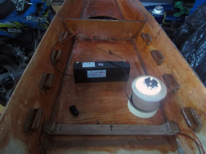
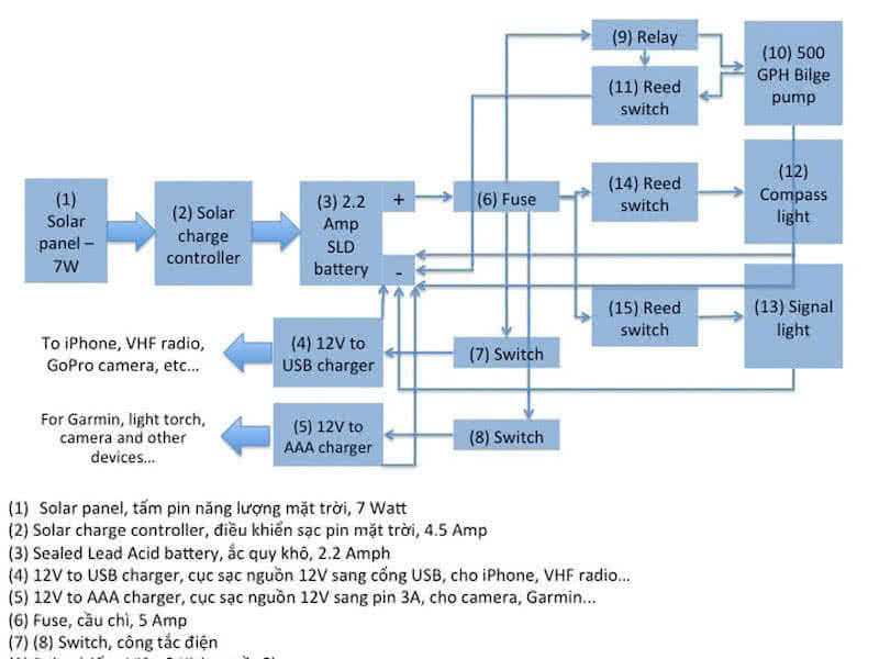
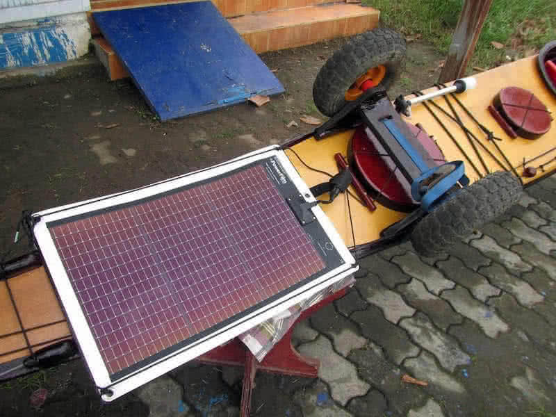
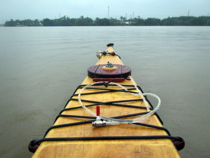
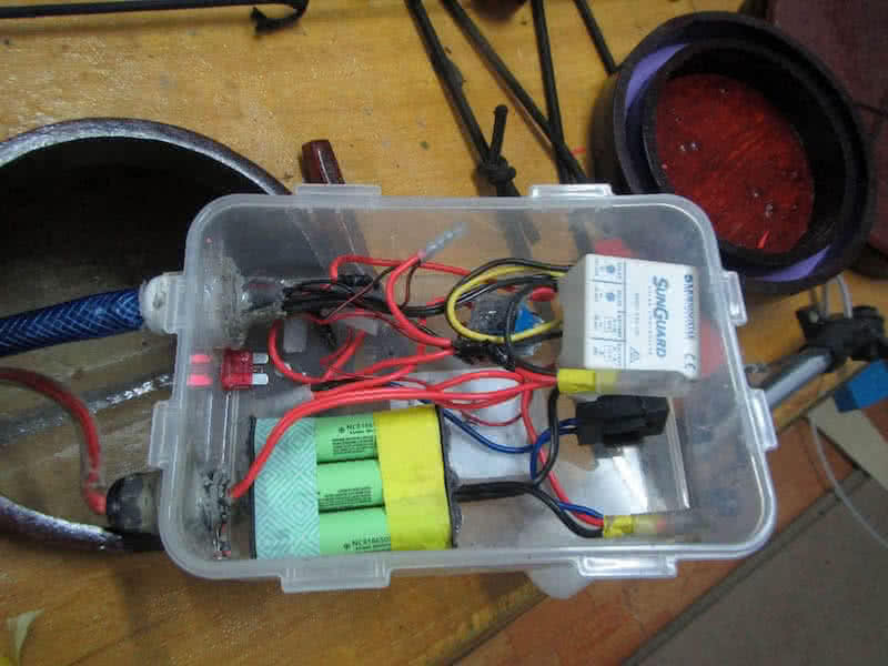
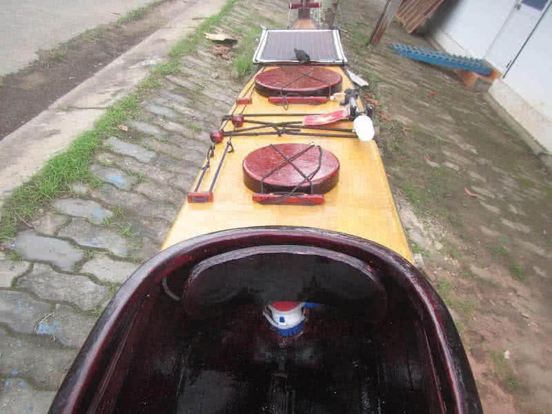
The progress slows down as I approach one of the last major phase of the project: electricity. This is a complex issue, the kayak would have a 7W solar panel, which charges into a 2.2 Amph SLD (Sealed Lead Acid) battery. The battery is used primarily is for powering the boat’s bilge pump, and secondarily, to charge various electronics devices: the iPhone, Garmin, VHF radio GoPro, camera, the compass’ and signal lights, etc…

Now working on the electrical parts of the project. From other renowned sea kayakers, I’ve long learnt about their electrical and electronic system. And my own experiences pointed out that, the need for a battery system to run a bilge pump (and to power various other devices) is very urgent and obvious. From the very early phases of this project, I’ve been thinking over and over again about it.
The system would have a solar panel, to charge into a SLD (sealed lead acid) battery. The battery is used to power the bilge pump, its primary purpose. But since now I have a 12V DC electric system onboard, I could use it to: illuminate the boat’s compass, power the signal light, and to charge various electronic devices: the iPhone, the VHF radio, the Garmin, cameras, etc… Basically, I want an independent system that power all.
First is the compass light, some white LED sources to illuminate the compass in case of paddling at night. I could just buy a compass with built – in lighting, but those such compasses are not readily available in the local market, and usually they’re a bit oversized for a tiny boat like Serene – 2. So I decided to modify my current compass to accommodate 4 white LED bulbs, the result is beautiful (1st & 2nd image)!
The most special thing in my electrical system is… the reed switch, a sealed electric switch which could be activated by a small piece of magnet (3rd image). That way, the switches could be hide and sealed inside the hull, completely covered in epoxy to protect them from water, and they could be turned on / off by the presence of some small pieces of magnet outside of the hull. I’ve found the idea… simply brilliant!
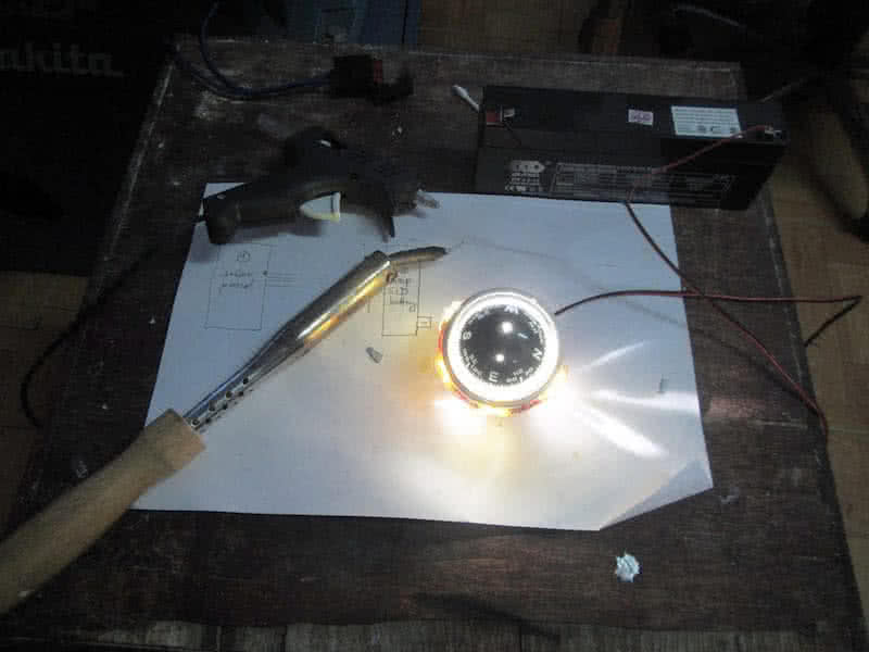
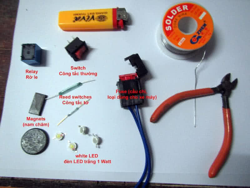
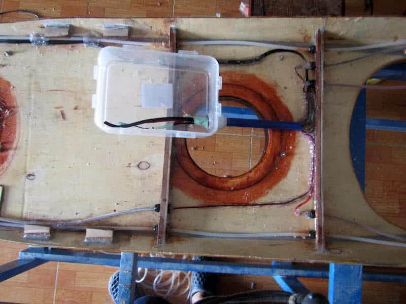
Next is running the electric wires. I want them to be completely waterproof, so every wire running is placed inside plastic tubes for additional protection. First image: I solder 3 reed switches with wires, place them inside the small wooden bar, seal it completely with epoxy, and glue them under deck inside the cockpit. The letters C, P, L mark the positions of the switches for: compass, pump and light.
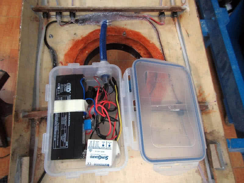
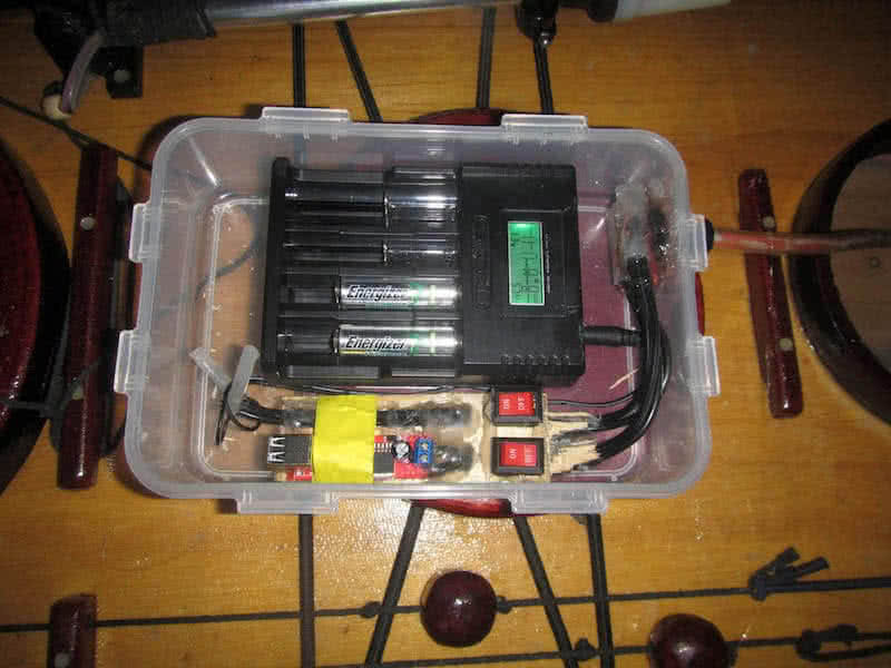
All wiring runs back to the day hatch, where a central box housing the main battery. I just use a LOCK & LOCK plastic box, it’s pretty much very watertight, if you close it properly. All wiring tubes would be connected to the box through cable glands with silicone glue. Another issue solved is the relay, it took me an hour to figure out how the PCB relay wiring works! Luckily, I haven’t forgotten all electric knowledges learnt in college!
Since the reed switch is so tiny, it usually can’t stand the amplitude of the current required by the bilge pump. So the reed switch is used to activate another switch (the relay), which can handle the current (it’s so good a feeling to hear a small ‘click, click’ sound when the relay is activated / deactivated)! The electrical, electronic parts of the project is not as hard as I’ve expected, all is done quite neatly!
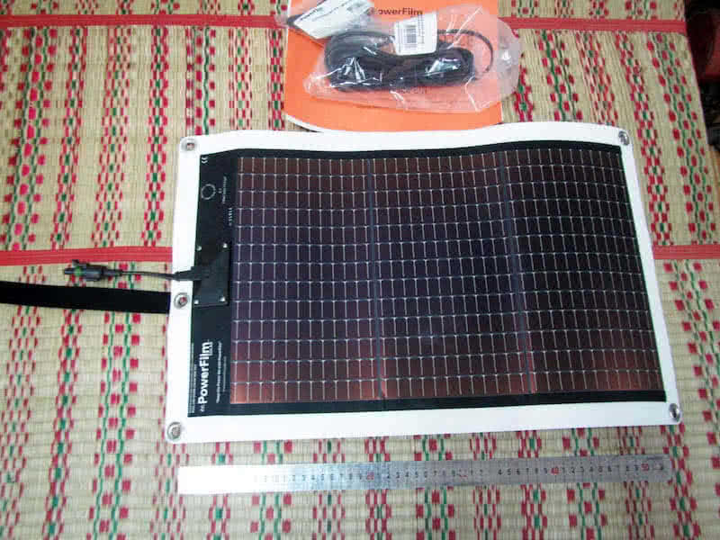
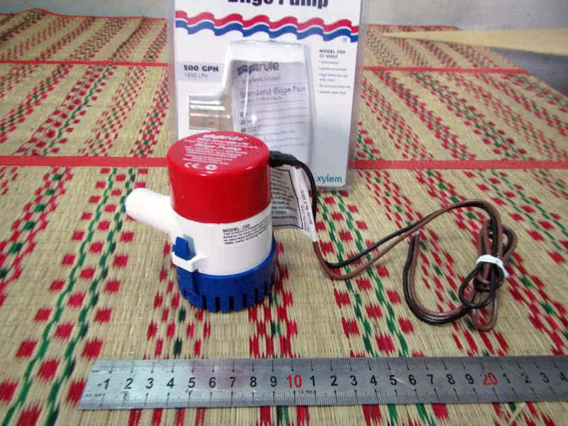
Today, most equipments I ordered from Amazon has arrived: the PowerFilm 7W rollable solar panel, the SunGuard 4.5 Amp solar charge controller, the Rule 500 GPH (gallon per hour) bilge pump, a marine signal light, one Stohlquist “high – back” PFD… and some other things. I was feeling very good, as this phase of the project could be completed soon, and the boat is already somewhat quite near its completion!
Finished all electrical wiring and device testing. It looks simple, but actually, for me, there were lots of works. First is to figure out how the relay pins work. First image: I noted down the wiring diagram of a relay, the 2 pins on the right, one is NO (normally opened) and one is NC (normally closed). The middle pin on the left (the common pin) supplies power to the targeted devices (here is the compass light, just for testing).
The two other pins supply power to the relay itself, when powered on (decided by the reed switch), the relay switches from NC to NO position, hence supplying power to the compass light. All wirings runs back to a central point: the plastic waterproof wiring box, which houses the battery, the solar charge controller, the relay… It took me some times to install all in the box, connect the correct wires, check if everything works!
The PowerFilm solar panel shipped with a long water proof detachable cable, so I run the cable from the central compartment to further aft where the solar panel would be located. This cable runs through a cable gland to exit the deck, ended with a waterproof connecter. It’s not very nice to always have this connector on deck, but it’s convenient to disconnect the solar panel and stored away when it’s not in need.
There would be another waterproof box (connected to this wiring box which would be rarely opened) which houses the 12V – to – USB and the 12V – to – AA charger, which could be usually opened to put your various devices in for charging (iPhone, VHF radio…) But that would be in another later phase of the project. It now time to joint the hull and deck parts together to form the final boat shape!


It’s time to join the hull and deck, and now the boat takes its final shape! The gunwales are bevelled differently along their length to better accommodate the deck, paste some putty on the bevelled edges, then I press the hull and deck together, like the two halves of a peanut shell. Everything goes on quite smoothly, the bow and aft parts fit very well, just use some duct tapes to press them together.
In the middle part, there are some small gaps (about 3, 4 millimeters), so I need to fasten them with some cables. The bulkheads fit really well, firmly holding the deck and hull. To maximize the boat waterproof capability, I carefully fill the internal seams with some more putty at places which are still accessible by my arms. The whole thing is left overnight for the putty to set, permanently forming the boat shape!
The next morning, I carefully trim the deck part. Since the deck is cut oversized, it’s slightly larger than the hull, it need to be trimmed down to match the hull, apply some more putty here and there to fill some remaining gaps, then round the seams (the external sides) in preparation for glassing the hull. Months of preparation, consideration and hard works has finally “culminated” into a seeable, touchable object!
It seems that, at this point, the boat would be able to see water in no time. But actually, there’re lots of works ahead: glassing the hull, install the rudder, rudder control lines and pedals, fitting the bilge pump and signal light, sticking the vinyl decorations (text and boat eyes), fitting the compass and all those bungee cords, various other accessories, etc… and finally varnishing the whole thing with transparent PU paint.
After joining the hull and deck, the hull receives its final bottom glassing. The fiber fabric would overlap the deck about an inch, to better seal the joint. One little trick to make a clean, tidy line at the painting (or epoxy) boundary: mask the area to paint (or to fill with epoxy) with duct tape. Prior to applying (colored) paint or epoxy, brush the duct tape with a very thin layer of transparent paint (or epoxy).
Wait for the paint (or epoxy) to cure, than apply the (colored) paint (or epoxy). That way, the colored paint (or epoxy) won’t leak through the duct tape, cause no matter how good the duct tape is, paint (or epoxy) would leak through, causing a blurry, untidy line. Second image: masking with duct tape, prepare for glassing the hull. I run out of my fiberglass fabric roll after this task, also use up the last drop of epoxy!
The hull glassing receives an additional layer of fill coat, then another layer of epoxy at the 3 seams, then a slight sanding. I don’t sand much, just at some rough places. The color scheme for this kayak is also brown / yellow like my previous two boats, but this time, the colors would be much lighter. Next would goes in the vinyl decal decorations, then varnishing the whole hull and deck with transparent PU paint.
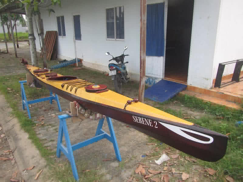
Since the deck’s space is used up for the 3 hatches, the bungee cords, the signal light and solar panel, and other accessories, all decorations would go to port and starboard sides: the boat eyes, boat name, and owner’s information! There’re many many other unnamed tasks required still to finish the boat, so I won’t hope to complete it until next week. However, the kayak would see water and start its trial paddling very soon!

The hull is painted with 2 layers of transparent PU paint. In this tropical weather, paint dries so fast, after about 3 or 4 hours, I can start the various deck fittings: mounting the forward hatch with compass on top (and compass light). The electric wires (housing inside a plastic tube) supplying power to the compass light also serves as a holding line, just in the rare case that the hatch could fall out.
The signal light is done the same way, connect the electric wires, seal them inside tube with silicone glue, test if the reed switch work. Until now, all 3 reed switches works well, I shouldn’t worry much about them, as reed switches, though tiny in size (less than 3 mm in diameter), are in fact very durable (rated at 100 000 times of turning on / off). In the silent night, I can hear the click, click sound of them turning on / off.
Fitting the bungee cords is quite straight forward. The anchor points (made from wood) work well enough, I just pull a thread through easily, don’t have to “prime” with a small steel wire like before. The forward bungee cords also run through 2 wooden blocks (see the third image), each house a magnet inside. I use the NdFeB (rare earth) magnets, which are really strong, they could turn on the reed switch 2 or 3 cm away.
Next, I would fit the rudder pedals, run the rudder control lines and see how all things works. Then comes the bilge pump, with the water hose, then the solar panel. The ugly thing is that you just don’t know how much power left in your battery, or if the solar panel is doing its job. So I ordered a “12V battery fuel gauge” from Amazon to read out the current capacity of my SLA battery. Below: a short video to show how the reed switches work!

Rectified one problem with the signal light, the bulb is too greedy, it eats up a lot of electricity and could potentially burn up the reed switch (I’ve noticed the reed switch has malfunctioned sometimes due to the high current). So I replace the bulb with 8 small white LEDs (1 Watt each). Some more soldering work, but finally it’s done, equally bright, but less power consumed, and safer for the switch.
Today, I installed and tested the rudder system. First is the two cable lines used to pull the rudder up and down. The 2 lines run back to the cockpit and are attached to 2 small wooden balls, with a short segment of bungee cord. Third image: the wooden balls and bungee cord. The bungee serves as a shock cord, in case the rudder should collide with some thing and kicked back, so that no damage would be done to the whole system.
One simple rule to operate the pull up / down lines: grab the ball that is further from the cockpit and pull it. Well, it sounds pretty simple, but useful enough, when in action, you just don’t have to think over and over again: which line is up, and which line is down! The two rudder control lines run back to inside the cockpit where they’re attached to the pedals via 2 small wooden jam cleats to adjust the lines’ tension.
All works well, but the pedal motions are not really smooth, because the bungee cords are not strong enough to pull the pedals back (once one pedal is kicked, I would just have to kick the other pedal to balance the rudder). But I would just leave them as they are for now, as they’re working already, would consider replacing the bungees with stronger ones (or revise the design a bit) later on.


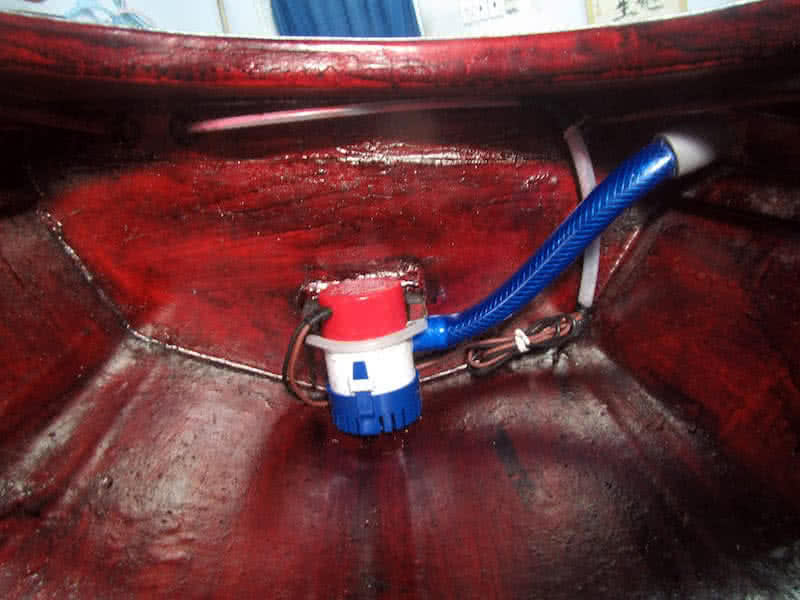
The bilge pump is a critical component of this Serene – 2 kayak. Empty out a flooded boat, or simply make your seat less wet, it gives you lots of confidence and convenience on long paddling trips. Today, I installed the bilge pump with its water hose (through a hole drilled on the port side). Electrical wires are connected and carefully sealed inside plastic tubes with silicone glue to make them really waterproof.
I wouldn’t want the whole system to collapse just because of one leaked electrical wire (anyhow, there’s still the fuse in case of a power surge, e.g: short circuit somewhere). Watch the short video below to see how the bilge pump works, it’s just so great! I would just move a wooden knob (the reed switch), and the water jumps out! The small “buzz, buzz” vibrating sound of the bilge pump is so fascinating!
One problem, however, due to the very deep V – bottom of the kayak, some small amount of water remains still at the bottom which could not be sucked out by the pump. That’s not a big problem anyhow, cause I would install a seat that raises me a few centimeters higher on the floor, and wouldn’t make my pant soaking wet. In the video, the water flow doesn’t look very strong, since the battery is already running low.
I would make more thorough testings to see how the whole system works in combination: battery, solar panel, lights, and bilge pump! But I would wait until the 12V battery “fuel gauge” shipped from Amazon, so that I can have exact measures on the battery usage, how many times it could pump out a boatful of water. It’s important to understand how your system works, so that you could make good uses of them on longer journeys!
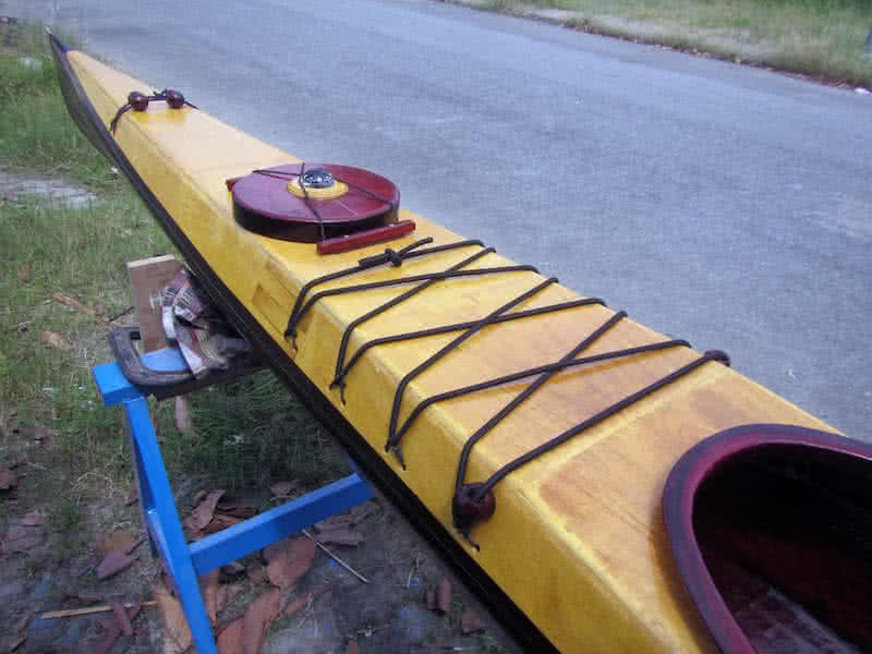

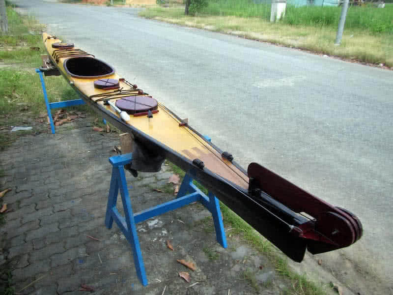
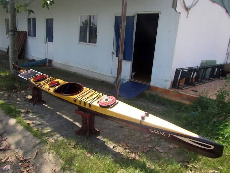
Sticking the vinyl decal decorations is among the last steps that complete the kayak. Since the deck spaces are almost used up for various accessories, the boat names and owner’s informations go onto the port and starboard sides instead, and the boat eyes intrinsic for any Vietnamese boat of course! The solar panel is tied on the aft deck, stretched with two short wooden spars, and lines through its grommets.
There’re some more items to be built or fitted for this kayak: the seat, the carriage for transporting the boat. I would rebuild my previous carriage, reuse the 2 wheels, but build it lighter and smaller, to easier carry it on the aft deck. The seat and back rest are also important parts, but those would be postponed to a later phase of the project. Also, I’m still waiting for my spray skirt to be shipped from Amazon.
After sticking the vinyl decal decorations, the bottom receives additional 2 layers of transparent PU paint, making them 3 layers in total for the bottom (the deck only received 2 layers), protecting the vinyls. The handle line pulling through a hole drilled at the bow (with a wooden block inside) is just a simple hang – man knot, the kayak has no handle at the stern, since the rudder has taken up all the space.
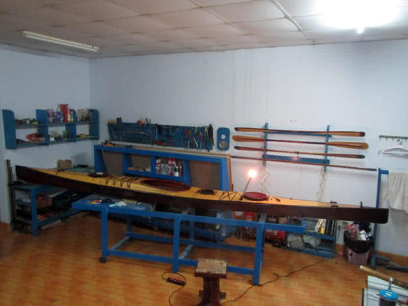
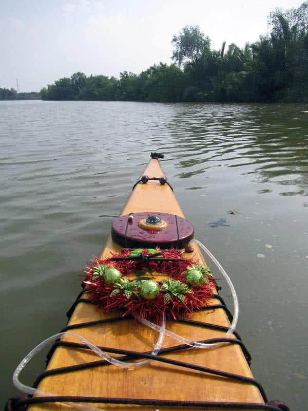
It’s so good a feeling to see the boat completed! Looking back on the building progress, there’re still things that I’m not really pleased with, in building quality, in the look & feel, in equipments… But I believe this is my best boat so far, accommodating various small design changes that I’ve found neccessary from my paddling experiences. I should start trialling the kayak soon, to see how she would behave on water!

Made the first trialling of my kayak today, a short 10 km paddling just to verify if everything works! All goes smoothly, hurray! The solar panel is adding juice to the battery, could see that obviously since the lights have become more intense, and pump has become much stronger (I almost used up the battery the day before). Under this tropical sun, that wouldn’t be a hard task for the solar cells, I guess!
The rudder works nicely, the pedals could be easily kicked by my legs, changing direction instantly. The pedals movements could be improved however, to become lighter and more responsive. Every parts of the boat simply just work! And the paddles also, I’m feeling pleased with the new paddles. And for the main part, the boat itself… it feel just a bit more stable (that’s what I was expecting for), but the hull now tracks much better!
It could go quite straight even without the rudder deployed. The feeling that the shorter boat is very steady, and could possibly go faster compared to my previous Serene – 1 kayak. Though the LOA (length over all) of Serene – 2 is shorter, its LWL (length waterline) is pretty much the same. The higher free board makes climbing into the boat a bit more difficult, but that’s not a problem, cause the cockpit now is a bit larger.
The slightly higher free board is very important, it should keep water out of the deck for many of the times, and hence waves shouldn’t threaten flooding the hatches much. My overall feeling is very pleasing, for those months of efforts put into the watercraft! But 10 km is too short, I need to trial the new kayak more, and record the routes by my Garmin, to really evaluate the boat’s performances in precise numbers.

Continue trialling my newly – built kayak with some short paddlings. The adjusted rudder pedals now work properly and smoothly. The battery system charged well, everything works as expected. One point I’ve found out is that, the SLA (Sealed Lead Acid) battery should be positioned upright for it to be charged to its maximum capacity. I was thinking about Lithium battery which is more compact, lighter, has more capacity…
But that would be later, maybe I should deploy a system of SLA and Lithium in parallel, as the SLA could provide short – bursts of hight current (required by the bilge pump), and the Lithium could provide a lower amperage for a longer period of time. Today, the Sea – to – summit spray skirt package arrived, the all – neoprene thick skirt fits well to the cockpit coaming, it should do its job of keeping the water out well!
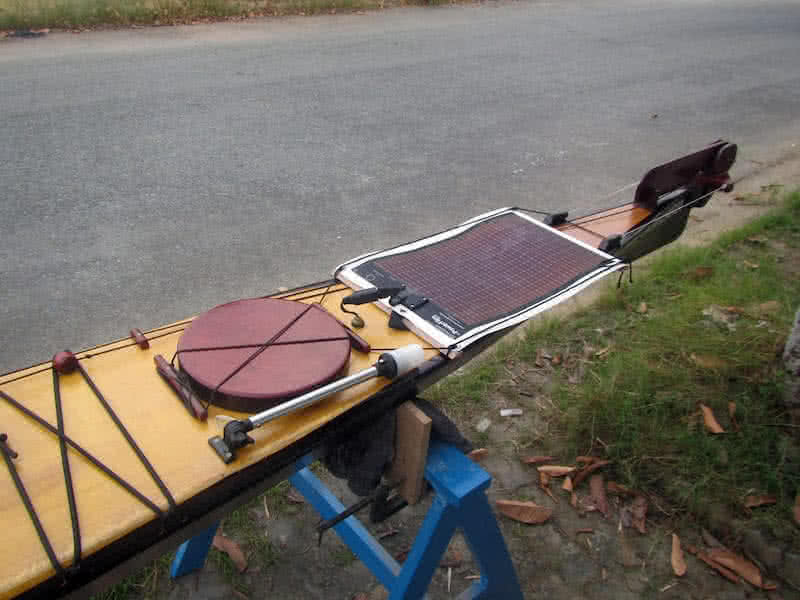
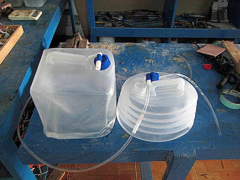
Also I’ve found out that I need to adjust the seat’s back rest a bit, it’s too high that strapping the skirt on could be a bit difficult. One important add-on to the kayak is the water drinking system. 2nd image: the 2 plastic water bags, from left to right: 10 and 8 liters respectively. The smaller oval – shaped water bag is put in the forward compartment, with a water tube running through a cable gland over the deck.
That way you can drink (suck the water out of the reservoir through the tube) without having to stop paddling. The low – lying bags would help with the boat’s stability, no more bulky water bottles needed, and the deck space would be clearer for other items of necessity. I’ve found this drinking system idea very practical, as I’ve lost quite some water bottles lashed to the bungee cords in heavy sea, when strong waves wash over the deck.

Many miscellaneous jobs required still to finish equipping my new kayak for upcoming paddling trips. First is adjusting the seat’s back rest, it’s a bit too high that strapping on the spray skirt could be a bit difficult. I simple cut down its back, then rivet the cut – out part onto the rest part. The hatches’ gaskets are cut from a thin (5 mm) rubber sheet (1st & 2nd images), should do their job of keeping the water out.
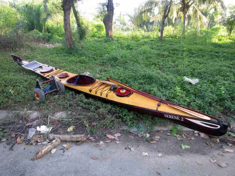
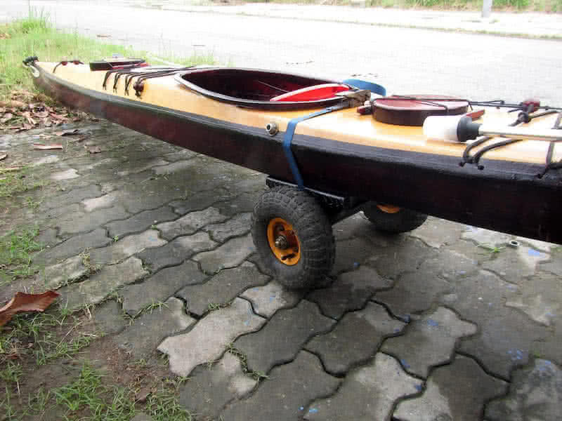
I made a new cart for transporting the boat on land, it’s just a smaller and lighter version of the previous one. I reused the pair of wheel, couldn’t reduce the wheels’ size since they have to be big enough so that the cart wouldn’t sink in when pulled on sand and mud. The result is quite satisfactory, big enough to easily transport the kayak, and small enough to not affect the boat stability when carried on the aft deck.
The list of small jobs to really finish the boat seems to be never ending, there’s always something I could do to improve, here and there, e.g: a mesh bag would be installed inside the cockpit, under the deck, to store various things I could need during a paddling trip, e.g: a small knife, a tiny light torch, a small monocular (to be equipped), reserved batteries for camera and GoPro, lighter, my tobacco box, etc…
It’s an interesting experience equipping a kayak for long paddling trips: everything need to be ready and accessible around your cockpit: food and drink, the back up paddle, the paddle float, radio and camera, everything… Fortunately, my newly purchased PFD has two pockets on the front side where I could hold some crucial things with me: the VHF radio, the Garmin and the Cannon waterproof small camera!

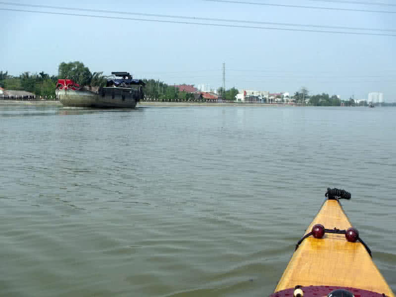
Made several short paddlings (10, 12 km) to trial my newly – built Serene – 2 kayak. The overall feeling is very pleasing, the boat is much easier to control compared to my previous one Serene – 1, and it’s faster, taking up momentum in just a few light strokes! But the velocity measures would be postponed until I could finish all equippings, all adjustments, and begin longer paddling to know precisely.
Yesterday, I had a capsize in my kayak, reason is that the seat raises the center of gravity (CG) by approximately 5 cm, just a very short distance but severely affect the boat stability. This is something I’d already knew in the designing phase, but still try to do the silly thing of installing the inappropriate seat. The solution is quite simple: remove the seat, just sit barely on the bottom, and build just a back – rest instead.
Apart from that, everything works well enough: the bilge pump, the rudder and rudder pedals, other electrical devices, etc… The shorter hull reacts more sensitively to load balancing, the kayak needs to be trimmed a little bit further aft to reach its most stable point. I’m especially happy with the rudder, to give a decisive conclusion on the Rudder vs. Skeg debate: the Skeg is simply left too far behind to argue!
Only long paddling would tell, if there’re some significant improves in “economical speed”, the important point of a kayak designed for cruising: the minimum effort required to propel the boat on large distance and in prolonged period of time. It takes some more efforts and times to really complete harnessing my Andalusian horse and make it ready for sea paddling trips in this Northern monsoon wind season!

Continue trialling and adjusting various boat equipments. The 2.2 Amph SLA battery works, but not to my expectation, first, it’s too heavy, second, its capacity is quite small, and third, the battery doesn’t hold its electricity for too long, about 2 days without charging and the battery would exhaust… After consulting with some other paddlers, I’ve decided to replace it with 3 Lithium cells, the results are just… superb!
I now have about 10 Amph in the very small 3 Li-ion cells, almost 5 times more the capacity, and 5 times less the weight, yet 5 times the price, advancements in battery technologies is just amazing! According to one of my friend, an “expert” in electric and electronic devices, the Li-ion would usually last longer, and compared to the SLA, with zero maintenance cost. After replacing the battery, I fitted the last electrical components.
The AA charger and the USB charger, they’re positioned inside another waterproof box, connected to the battery box with electrical wires inside a plastic tube. The installation is pretty easy, the two devices are connected via two switches, simply put your iPhone (or your VHF radio, or your AA batteries) into the box, turn on the switch, close the box, and let the Li-ion cells, plus the solar panel do their job!
Also, I’ve removed the plastic seat, replace it with just a back – rest instead. The back – rest is built from plywood, bent into a curved shape, covered on 1 side with a rubber sheet (to make your back resting more comfortable), and fitted into the cockpit aft, it could be rotated slightly to suit my various sitting positions. These are last updates for the boat in this 2016 year, now it’s time to just enjoy the water!
Made several longer paddlings (15 ~ 20 km) to see how the kayak would perform. As with all my previous boats, it takes some little time for me to adapt myself to a new boat, in particular, the primary stability. Each kayak differs by a little, after a few dozens of kilometers, I would feel more comfortable and confident with the boat’s motions. Only after that, the speed measures could be evaluated more accurately.
The Garmin GPS data shows that I could sustain about 7 kmph with my new kayak. That’s pretty much very good, though only slightly better compared to Serene – 1 (it was about 6.5+ kmph). The 7 kmph value is very closed to the average speed that other famous sea kayakers would usually make. The improvement at this point is very critical, since I can hardly make any more gain without sacrifices to the boat stability.
The weather this season is quite ideal for paddling, the temperature is dropping to around 20 ~ 25 degree (Celsius). The Northern wind is blowing, but much a lesser amplitude compared to this time last year. But too bad, I’m quite busy with my works and can’t spend much time on water, my paddling performance is not truly at its peak, so it’s still early to say more about the new kayak’s performance characteristics.
Anyway, I’m feeling very pleased with my new kayak, and I think that with more training, I could bring her to a much better performance level. Some more works required still on the kayak though, in essence, I would have to rework the USB – charging circuit, the current one is over – powered by the 3 powerful Lithium cells and wouldn’t work very well. Christmas and New Year season is coming, happy season to everyone!

Made some more longer paddlings (20 ~ 25 km) to get to really know her, my newly – built Serene – 2 kayak. It’s not until now that I could get myself familiarized with the boat’s primary stability, which could be really “frightening” to most novice paddlers. In reality, Serene – 2 is “more stable” compared to Serene – 1, but with a much higher free board, the secondary stability comes a bit later, to assure that everything is alright!
Actually, I’m a bit concerned about the boat’s primary stability, cause it has lots of V – bottom the under side. I would need to trail the kayak in its full capacity, to really make sure that the boat reaches its expected stability when fully – loaded with gears for a multiple – days paddling trip. The “fearful, uneasy feeling” caused by the low primary stability should not be taken for granted at all, even when I know that it’s safe.
Cause you would virtually going nowhere when all the time, you’re just worrying about it, worrying that something (a potential capsize) would happen. I’m pretty sure that the boat would be fine at its designed displacement, but only trialling would tell precisely. Looking back at all my boat building, boat playing times, lots of fearful moments, lots of self – doubting, self – disappointments, self – blaming, etc…
But that’s the nature of boating things, of “adventures” on the water. It requires lots of practicing and improving, to make sure that everything is right, that everything just works. My paddling performance is really really bad lately, with very little training ever since my last 9 days paddling trip in June. Obviously, something need to be improved here, and that would be among my resolutions in the coming new year!
PHOTO ALBUMS
For more details, see the photo albums below:


